.A complete Parts List is available at www.MillerWelds.com
3-5. Installing Work Clamp
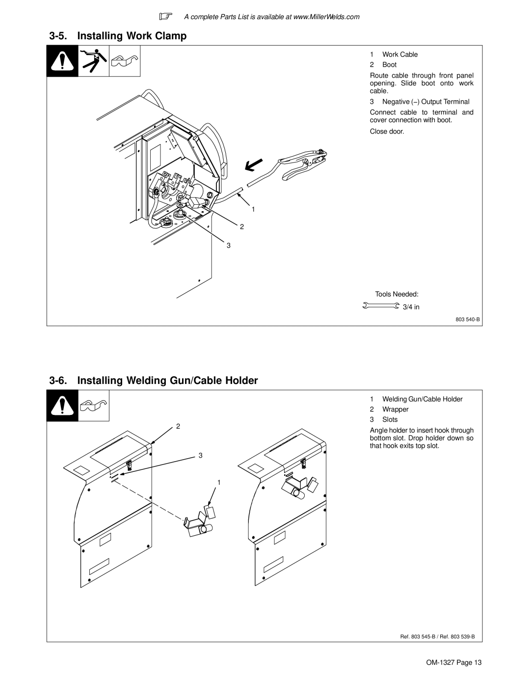
1 Work Cable
2 Boot
Route cable through front panel opening. Slide boot onto work cable.
3 Negative (−) Output Terminal
Connect cable to terminal and cover connection with boot.
Close door.
1
2
3
Tools Needed: ![]() 3/4 in
3/4 in
803
3-6. Installing Welding Gun/Cable Holder
2
3
1Welding Gun/Cable Holder
2Wrapper
3Slots
Angle holder to insert hook through bottom slot. Drop holder down so that hook exits top slot.
1
Ref. 803