.A complete Parts List is available at www.MillerWelds.com
6-4. Changing Drive Roll and Wire Inlet Guide
|
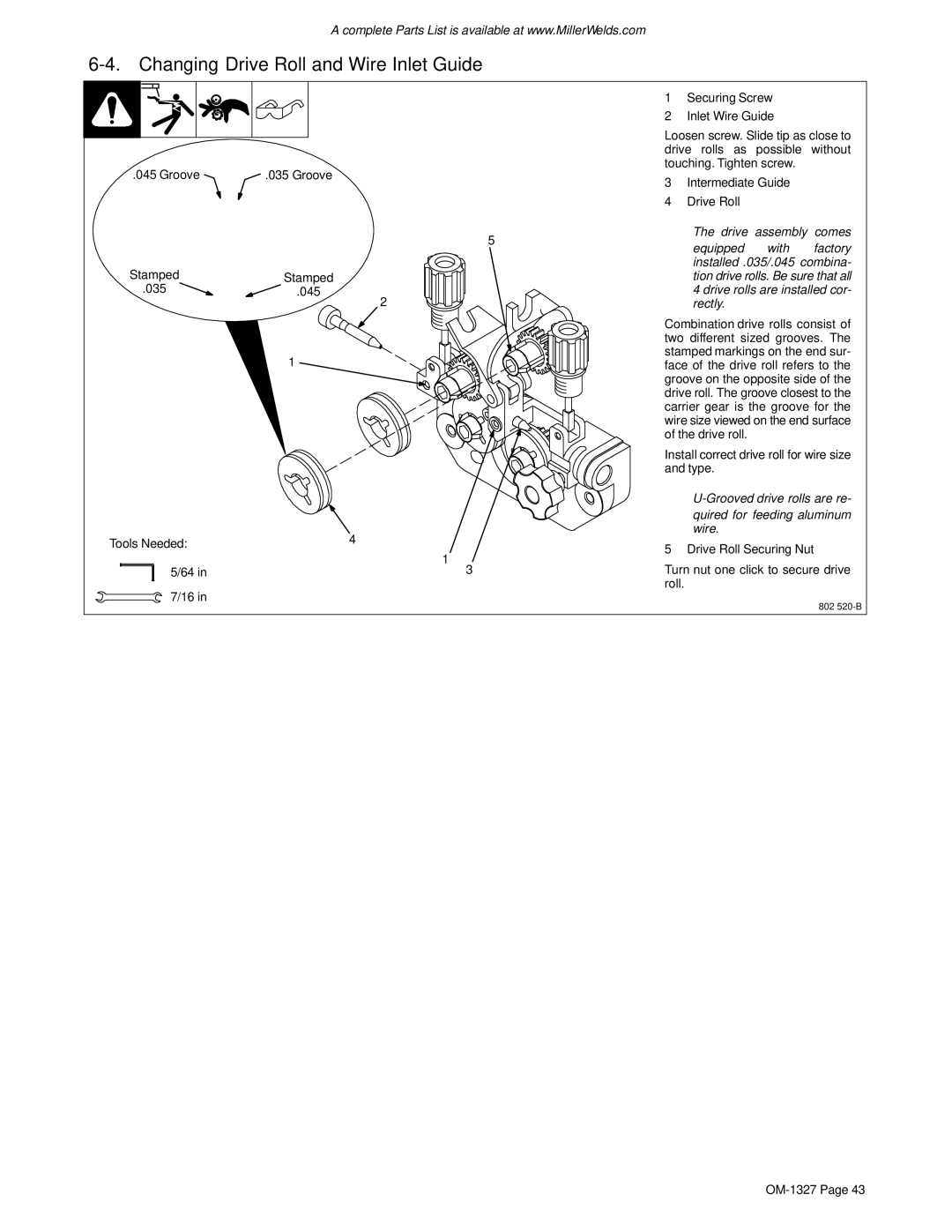
| 1 | Securing Screw |
| ||
|
| 2 | Inlet Wire Guide |
| ||
|
| Loosen screw. Slide tip as close to | ||||
|
| drive rolls as possible without | ||||
.045 Groove | .035 Groove | touching. Tighten screw. |
| |||
3 | Intermediate Guide |
| ||||
|
|
| ||||
|
| 4 | Drive Roll |
|
| |
|
| .The drive assembly comes | ||||
|
| 5 | equipped | with | factory | |
|
|
| ||||
Stamped |
|
| installed .035/.045 combina- | |||
Stamped |
| tion drive rolls. Be sure that all | ||||
.035 | .045 |
| 4 drive rolls are installed cor- | |||
| 2 |
| rectly. |
|
| |
|
| Combination drive rolls consist of | ||||
|
| two different sized grooves. The | ||||
| 1 | stamped markings on the end sur- | ||||
| face of the drive roll refers to the | |||||
|
| groove on the opposite side of the | ||||
|
| drive roll. The groove closest to the | ||||
|
| carrier gear is the groove for the | ||||
|
| wire size viewed on the end surface | ||||
|
| of the drive roll. |
|
| ||
|
| Install correct drive roll for wire size | ||||
|
| and type. |
|
| ||
|
| |||||
|
|
| quired for feeding aluminum | |||
| 4 |
| wire. |
|
| |
Tools Needed: | 5 Drive Roll Securing Nut | |||||
| ||||||
| 1 | |||||
|
|
|
|
| ||
5/64 in | 3 | Turn nut one click to secure drive | ||||
|
| roll. |
|
|
| |
7/16 in
802