Main
Millermatic 350 And Millermatic 350P
From Miller to You
Page
TABLE OF CONTENTS
SECTION 1 SAFETY PRECAUTIONS - READ BEFORE USING
1-1. Symbol Usage
.
1-2. Arc Welding Hazards
ELECTRIC SHOCK can kill.
ARC RAYS can burn eyes and skin.
WELDING can cause fire or explosion.
FLYING M E TAL o r DIRT can injure eyes.
BUILDUP OF GAS can injure or kill.
MAGNETIC FIELDS can affect Implanted Medical Devices.
1-3. Additional Symbols For Installation, Operation, And Maintenance
FIRE OR EXPLOSION hazard.
FALLING UNIT can cause injury.
OVERUSE can cause OVERHEATING
FLYING SPARKS can cause injury.
1-4. California Proposition 65 Warnings
1-5. Principal Safety Standards
1-6. EMF Information
SECTION 2
2-1. Symboles utiliss
.
2-2. Dange rs relatifs au soudage larc
UNE DCHARGE LECTRIQUE peut entraner la mort.
DES PICES CHAUDES peuvent provoquer des brlures graves.
et
ro-
tre
LES FUMES ET LES GAZ peuvent
2-3.
e
Risque DINCENDIE OU DEXPLO- SION.
LA CHUTE DE LAPPAREIL peut blesser.
LEMPLOI EXCESSIF peut SUR- CHAUFFER LQUIPEMENT.
2-4. Proposition californienne 65 Avertissements
2-5. Principales normes de scurit
2-6. Information EMF
Page
SECTION 3 INSTALLATION
3-1. Specifications
WELDING AMPERES
% DUTY CYCLE
3-2. Duty Cycle And Overheating
3-3. Volt-Ampere Curve
3-4. Connecting To Weld Output Terminals
!
3-5. Installing W ork Clamp
3-6. Installing Welding Gun/Cable Holder
3-7. Installing W elding Gun
3-8. Connecting Spoolmatic) 15A Or 30A Gun
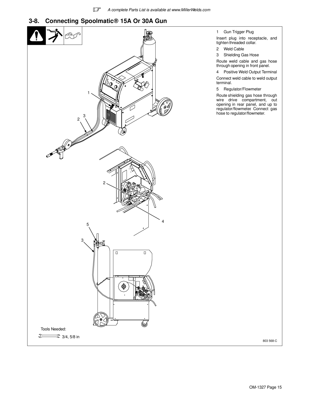
3-9. Connecting XR Edge, XR-A Gun, XR-A Python, Or XR - Aluma-Pro
.
3-10. Setting Gun Polarity For Wire Type
Changing Polarity
+
-
3-11. Installing Gas Supply
3-12. Installing Wire Spool and Adjusting Hub Tension
3-13. Electrical Service Guide
3-14. Selecting Input Voltage (200/230/460 Volt Models Only)
!
.
3-15. Selecting A Location And Connecting 3-Phase Input Power
!
3
3-16. Selection A Location And Connecting 1-Phase Input Power
!
1
3-17. Threading Welding Wire For MIG Gun
.
3-18. Threading W elding Wire For XR Edge, XR-A Gun, XR-A Python, Or XR - Aluma-Pro
.
IMPORTANT! For Aluminum PushPull welding. Thread hub tension nut loosely
IMPORTANT! For Aluminum PushPull welding.
3-19. Threading Welding Wire Through XR Guns
!
.
SECTION 4 OPERATION
4-1. Controls
.
4-2. MIG Mode
4-3. Jog Mode
.
4-5. MIG Gun-On-Demand
4-6. Pulse MIG Mode Voltage Adjustment
4-7. Pulse MIG Gun-On-Demand
4-8. Tip Saver
4-9. Weld Parameters For MIG Mode
Wire
Gas
Material
23.5 /220 Volts/Wirefeed Reference
4-10. Weld Parameters For Pulse Mode
WELDCHARTS
PULSECHART
PULSECHARPULSECHART
Gas WireMaterial
SECTION 5 PROGRAMMING
5-1. MIG Welding Mode
SETUP
OPERATION
ARC CONTROL
5-2. Pulse MIG Welding Mode
SETUP
OPERATION
ARC LENGTH
ARC CONTROL
5-3. Timers
5-4. Arc Times, Arc Starts, Hot Start (Aluminum Pulse Only), And Crater Fill
.
5-5. Setting Hot Start (Aluminum Pulse Only) Parameters
On
.
5-6. Setting Crater Fill
WFS
VOLT (MIG program) or ARCL (pulse
.
Page
Page
5-8. System Reset
SRST will appear on the left display and OFF
.
5-9. Motor Calibration Function
.
Data sav e
.
5-10. Set Up Push Motor Torque (SUP) Or Reset (rES)
SECTION 6 MAINTENANCE &TROUBLESHOOTING
6-1. Routine Maintenance
!
6-2. Overheating
!
6-3. Measuring Input Capacitor Voltage
6-4. Changing Drive Roll and Wire Inlet Guide
Page
.
6-6. Troubleshooting
Trouble Remedy
Page
Page
Page
Page
Page
SECTION 8 PARTS LIST
8-1. Drive Roll And Wire Guide Kits .
.
Wire Diameter Fraction Decimal Metric
Kit No.
Page
Page
Warranty Questions?
Call 1-800-4-A-MILLER for your local Miller distributor.
Effective January 1, 2007 (Equipment with a serial number preface of LH or newer)
Please complete and retain with your personal records.
For Service
Always provide Model Name and Serial/Style Number.
Contact a DISTRIBUTOR or SERVICE AGENCY near you.
Owners Record