.A complete Parts List is available at www.MillerWelds.com
SECTION 4 − OPERATION
4-1. Controls
|
|
|
|
|
|
|
|
|
|
|
|
|
|
|
|
|
|
|
|
|
|
|
|
|
|
|
|
|
|
|
|
|
|
|
|
|
|
|
|
|
|
|
|
|
| 11 | |
|
|
|
|
|
|
|
|
|
| ||
|
|
|
|
|
|
|
|
|
| ||
10 |
|
| |||||||||
1
2 ![]()
![]()
![]()
![]()
3
4
5
6
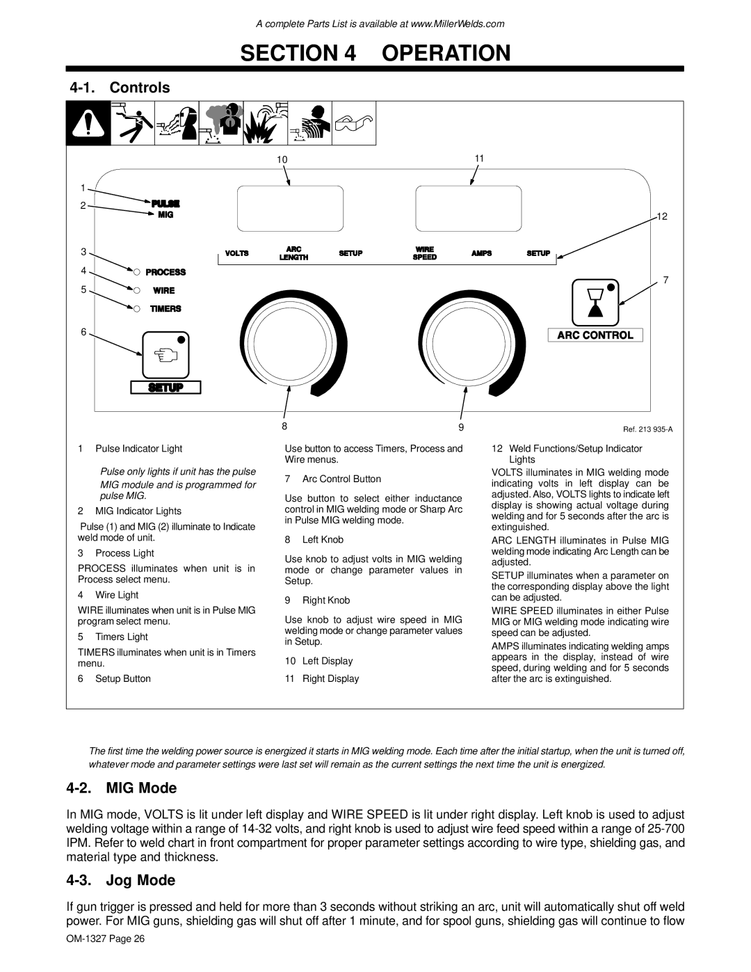
1 Pulse Indicator Light
.Pulse only lights if unit has the pulse
MIG module and is programmed for pulse MIG.
2 MIG Indicator Lights
Pulse (1) and MIG (2) illuminate to Indicate weld mode of unit.
3 Process Light
PROCESS illuminates when unit is in Process select menu.
4 Wire Light
WIRE illuminates when unit is in Pulse MIG program select menu.
5 Timers Light
TIMERS illuminates when unit is in Timers menu.
6 Setup Button
8 | 9 |
Use button to access Timers, Process and Wire menus.
7 Arc Control Button
Use button to select either inductance control in MIG welding mode or Sharp Arc in Pulse MIG welding mode.
8 Left Knob
Use knob to adjust volts in MIG welding mode or change parameter values in Setup.
9 Right Knob
Use knob to adjust wire speed in MIG welding mode or change parameter values in Setup.
10Left Display
11Right Display
12
7
Ref. 213
12Weld Functions/Setup Indicator Lights
VOLTS illuminates in MIG welding mode indicating volts in left display can be adjusted. Also, VOLTS lights to indicate left display is showing actual voltage during welding and for 5 seconds after the arc is extinguished.
ARC LENGTH illuminates in Pulse MIG welding mode indicating Arc Length can be adjusted.
SETUP illuminates when a parameter on the corresponding display above the light can be adjusted.
WIRE SPEED illuminates in either Pulse MIG or MIG welding mode indicating wire speed can be adjusted.
AMPS illuminates indicating welding amps appears in the display, instead of wire speed, during welding and for 5 seconds after the arc is extinguished.
.The first time the welding power source is energized it starts in MIG welding mode. Each time after the initial startup, when the unit is turned off, whatever mode and parameter settings were last set will remain as the current settings the next time the unit is energized.
4-2. MIG Mode
In MIG mode, VOLTS is lit under left display and WIRE SPEED is lit under right display. Left knob is used to adjust welding voltage within a range of
4-3. Jog Mode
If gun trigger is pressed and held for more than 3 seconds without striking an arc, unit will automatically shut off weld power. For MIG guns, shielding gas will shut off after 1 minute, and for spool guns, shielding gas will continue to flow