A. Standard Module Connections
YREAD SAFETY BLOCKS at start of Section 4-6 before proceeding.
INADEQUATE WORK CABLE CONNECTIONS can cause serious damage to input power service and create a hazardous condition.
Connect an electrical cable of adequate size between the common work connection terminal and the workpiece whenever any mod- ule(s) is connected to use the frame connection terminal and the common work connection terminal.
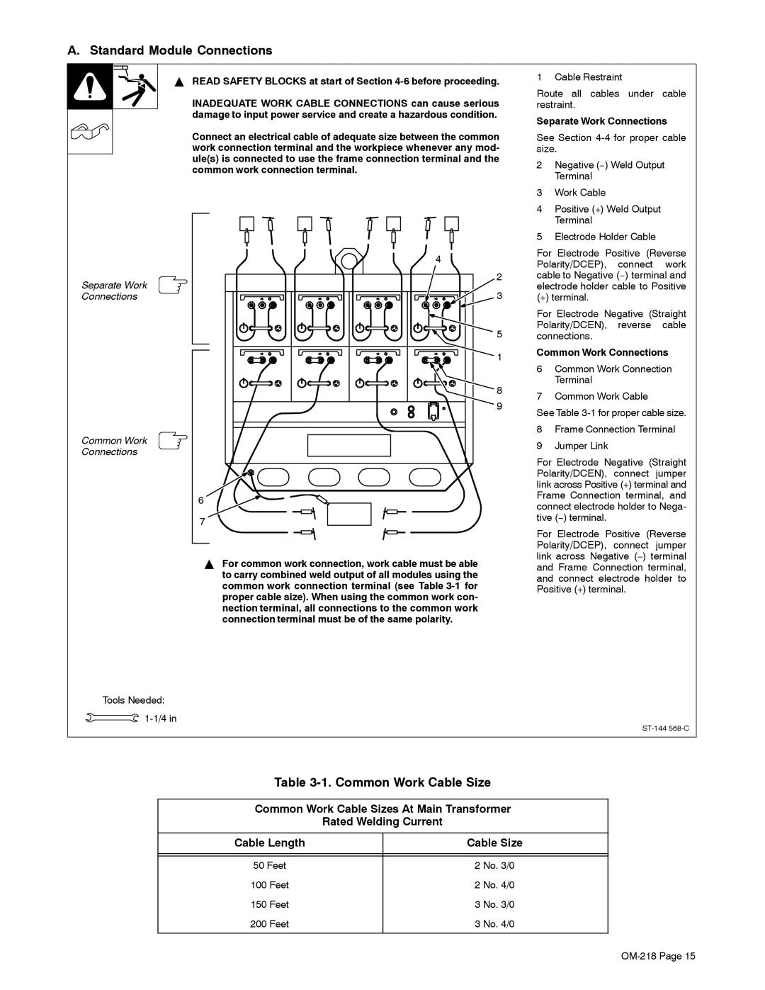
1 Cable Restraint
Route all cables under cable restraint.
Separate Work Connections
See Section
2Negative (−) Weld Output Terminal
3Work Cable
4Positive (+) Weld Output Terminal
5Electrode Holder Cable
Separate Work Connections
Common Work Connections
4
2 3
5
![]() 1
1
![]() 8
8
9
6
7
YFor common work connection, work cable must be able to carry combined weld output of all modules using the common work connection terminal (see Table
For Electrode Positive (Reverse Polarity/DCEP), connect work cable to Negative (−) terminal and electrode holder cable to Positive
(+) terminal.
For Electrode Negative (Straight Polarity/DCEN), reverse cable connections.
Common Work Connections
6Common Work Connection Terminal
7Common Work Cable
See Table
8Frame Connection Terminal
9Jumper Link
For Electrode Negative (Straight Polarity/DCEN), connect jumper link across Positive (+) terminal and Frame Connection terminal, and connect electrode holder to Nega- tive (−) terminal.
For Electrode Positive (Reverse Polarity/DCEP), connect jumper link across Negative (−) terminal and Frame Connection terminal, and connect electrode holder to Positive (+) terminal.
Tools Needed: ![]()
Table 3-1. Common Work Cable Size
Common Work Cable Sizes At Main Transformer
Rated Welding Current
Cable Length | Cable Size |
|
|
|
|
50 Feet | 2 No. 3/0 |
100 Feet | 2 No. 4/0 |
150 Feet | 3 No. 3/0 |
200 Feet | 3 No. 4/0 |
|
|