4-7. Remote Amperage Control Receptacle
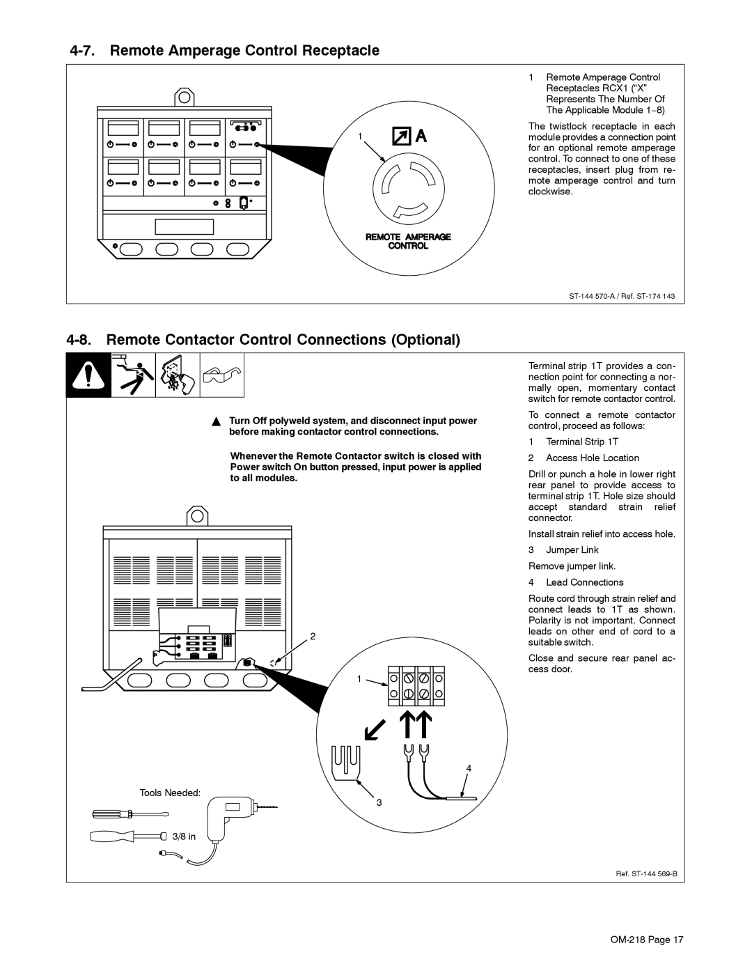
| 1 Remote Amperage Control |
| Receptacles RCX1 (“X” |
| Represents The Number Of |
| The Applicable Module 1−8) |
1 | The twistlock receptacle in each |
module provides a connection point | |
| for an optional remote amperage |
| control. To connect to one of these |
| receptacles, insert plug from re- |
| mote amperage control and turn |
| clockwise. |
4-8. Remote Contactor Control Connections (Optional)
YTurn Off polyweld system, and disconnect input power before making contactor control connections.
Whenever the Remote Contactor switch is closed with Power switch On button pressed, input power is applied to all modules.
2
1
4
Tools Needed:
3
![]() 3/8 in
3/8 in
Terminal strip 1T provides a con- nection point for connecting a nor- mally open, momentary contact switch for remote contactor control.
To connect a remote contactor control, proceed as follows:
1Terminal Strip 1T
2Access Hole Location
Drill or punch a hole in lower right rear panel to provide access to terminal strip 1T. Hole size should accept standard strain relief connector.
Install strain relief into access hole.
3Jumper Link
Remove jumper link.
4Lead Connections
Route cord through strain relief and connect leads to 1T as shown. Polarity is not important. Connect leads on other end of cord to a suitable switch.
Close and secure rear panel ac- cess door.
Ref.