Item | Dia. | Part | Description | Quantity | ||
| No. | Mkgs. | No. | |||
|
|
|
|
| Figure | |
|
|
|
|
|
|
|
. . . | 1 | . . . . | . . . . . . . | . . . +086 855 | . . PANEL, front lower | . . . 1 |
. . . | 2 | . . . . | . . . . . . . | . . . . 217 136 | . . LABEL, warning electric shock | . . . 1 |
. . . | 3 | . . . . | . . . . . . . | . . . . 174 847 | . . LABEL, general precautionary | . . . 1 |
. . . | 4 | . . . . | . . . . . . . | . . . . 004 449 | . . RING, spacer switch | . . . 2 |
. . . | 5 | . . . . | . . . . . . . | . . . . 204 360 | . . LIGHT, ind white lens (includes) | . . . 1 |
. . . 6 | . . . . . PL1 . | . . . *027 633 | . . . . BULB, incand bayonet base 8V | . . . 1 | ||
. . . | 7 | . . . . | . . . . . . . | . . . . 204 361 | . . . . LENS, light ind white | . . . 1 |
. . . 8 | . . . . . Start | . . . . 011 033 | . . PUSH BUTTON, operator black | . . . 1 | ||
. . . 9 | . . . . . Start | . . . . 011 035 | . . CONTACT BLOCK, NO PB | . . . 1 | ||
. . . 10 . . . . | . Stop | . . . . 011 036 | . . CONTACT BLOCK, NC PB | . . . 1 | ||
. . . 11 | . . . . | . Stop | . . . . 011 034 | . . PUSH BUTTON, operator red | . . . 1 | |
. . . 12 . . . . | . . . . . . . | . . . . 016 585 | . . COVER, dust | . . . 1 | ||
. . . 13 . . . . | . RC2 | . . . . 604 176 | . . RECEPTACLE, str dx grd 2P3W 15A 125V | . . . 1 | ||
. . . | . . . | . . . . | . . . . . . . | . . . . 073 690 | . . PLUG, str grd armd 2P3W 15A 125V P & S 5266DF |
|
. . . 14 . . . . | . CB1 | . . . . 083 432 | . . SUPPLEMENTARY PROTECTOR, man reset 1P 10A 250V | . . . 1 | ||
. . . 15 . . . . | . . . . . . . | . . . . 026 758 | . . BOOT, circuit breaker | . . . 1 | ||
. . . 16 . . . . | . . . . . . . | . . . . 038 805 | . . COVER, rcpt weatherproof duplex | . . . 1 | ||
. . . 17 . . . . | . . . . . . . | . . . . 004 450 | . . BOOT, PB red | . . . 1 | ||
. . . 18 . . . . | . . . . . . . | . . . . 004 451 | . . BOOT, PB black | . . . 1 | ||
. . . 19 . . . . | . . . . . . . | . . . . . . . . . . . . . | . . NAMEPLATE, (order by model and serial number) | . . . 1 | ||
. . . 20 . . . . | . . . . . . . | . . . . 085 382 | . . LABEL, component location | . . . 1 | ||
1
2
3
4
7 18 17
.Hardware is common and not available unless listed.
5
6Includes Item 7
8
9
10
11 12
13
14
19 | 16 | 20 | 15 |
|
155
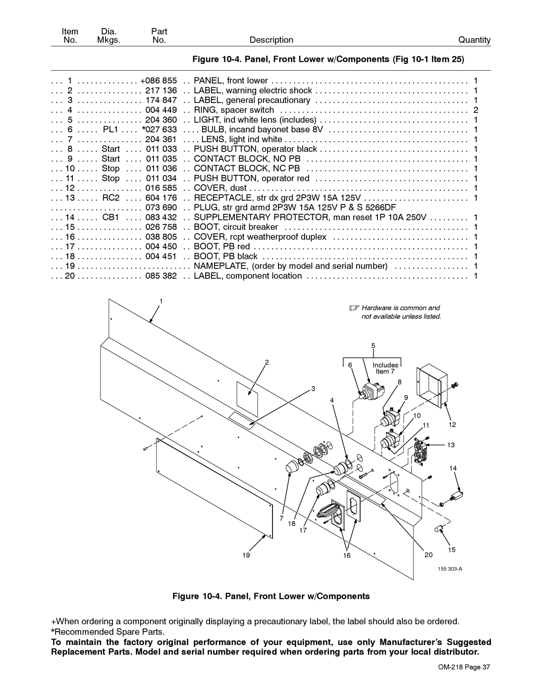
Figure 10-4. Panel, Front Lower w/Components
+When ordering a component originally displaying a precautionary label, the label should also be ordered. *Recommended Spare Parts.
To maintain the factory original performance of your equipment, use only Manufacturer’s Suggested Replacement Parts. Model and serial number required when ordering parts from your local distributor.
