B. Parallel Module Connections
YREAD SAFETY BLOCKS at start of Section
Use single cables of adequate capacity to carry the total combined am- perage of the paralleled modules (see Section
Securely cover common connections with proper insulating materials.
Set the Amperage Adjustment controls on all paralleled modules to provide the same output.
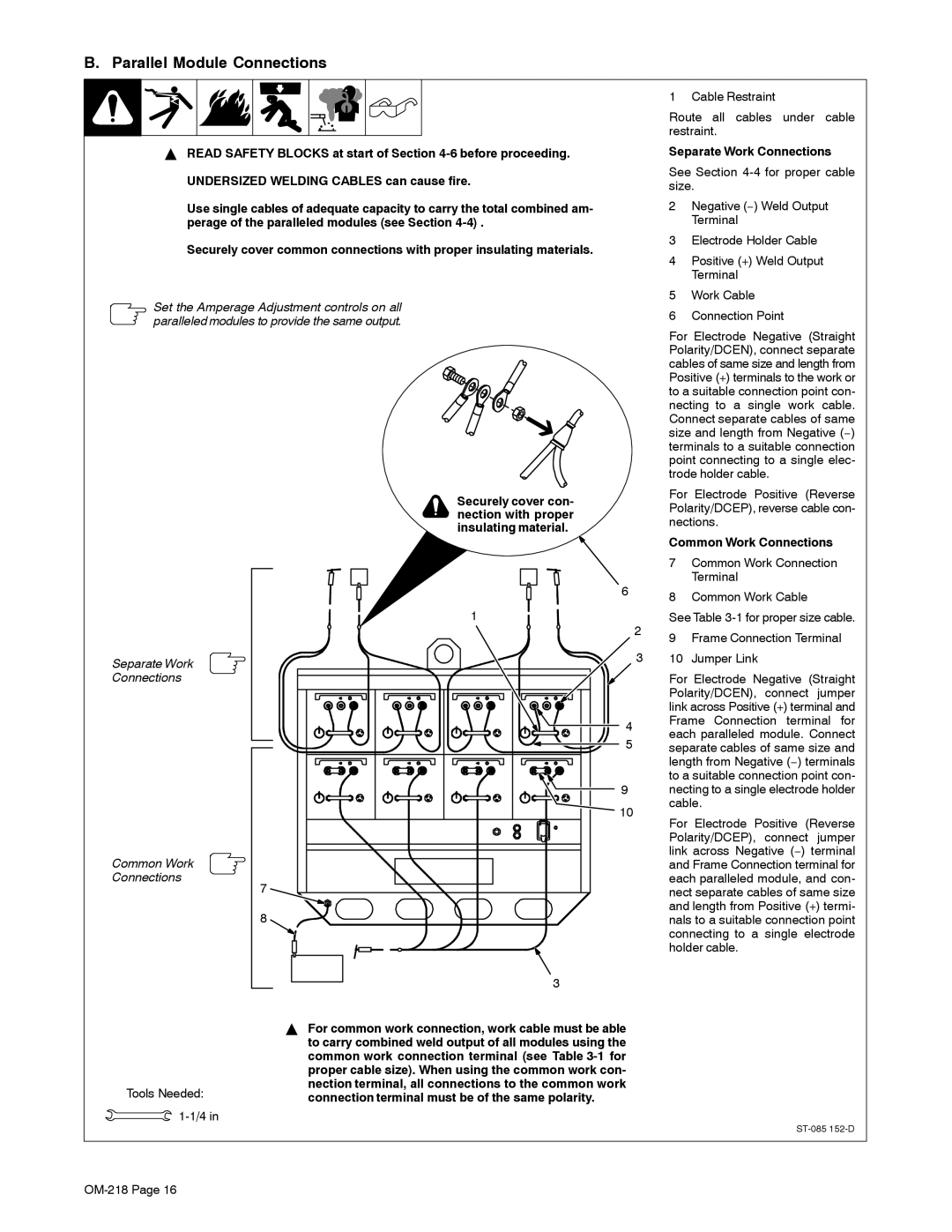
Securely cover con- nection with proper insulating material.
1 Cable Restraint
Route all cables under cable restraint.
Separate Work Connections
See Section
2Negative (−) Weld Output Terminal
3Electrode Holder Cable
4Positive (+) Weld Output Terminal
5Work Cable
6Connection Point
For Electrode Negative (Straight Polarity/DCEN), connect separate cables of same size and length from Positive (+) terminals to the work or to a suitable connection point con- necting to a single work cable. Connect separate cables of same size and length from Negative (−) terminals to a suitable connection point connecting to a single elec- trode holder cable.
For Electrode Positive (Reverse Polarity/DCEP), reverse cable con- nections.
Common Work Connections
Separate Work
Connections
Common Work
Connections
Tools Needed: ![]()
7
8
6
1
2
3
4
5
9
![]() 10
10
3
YFor common work connection, work cable must be able to carry combined weld output of all modules using the common work connection terminal (see Table
7Common Work Connection Terminal
8Common Work Cable
See Table
9Frame Connection Terminal
10Jumper Link
For Electrode Negative (Straight Polarity/DCEN), connect jumper link across Positive (+) terminal and Frame Connection terminal for each paralleled module. Connect separate cables of same size and length from Negative (−) terminals to a suitable connection point con- necting to a single electrode holder cable.
For Electrode Positive (Reverse Polarity/DCEP), connect jumper link across Negative (−) terminal and Frame Connection terminal for each paralleled module, and con- nect separate cables of same size and length from Positive (+) termi- nals to a suitable connection point connecting to a single electrode holder cable.