B. Connecting Input Power
8
7
![]()
![]() 10
10
9
4
6
2
1
| L1 | (U) |
6 | L2 | (V) |
| L3 | (W) |
Tools Needed: |
|
4 | |
| |
3/8 in | 3 |
|
5
ssb2.4* 1/94 − Ref.
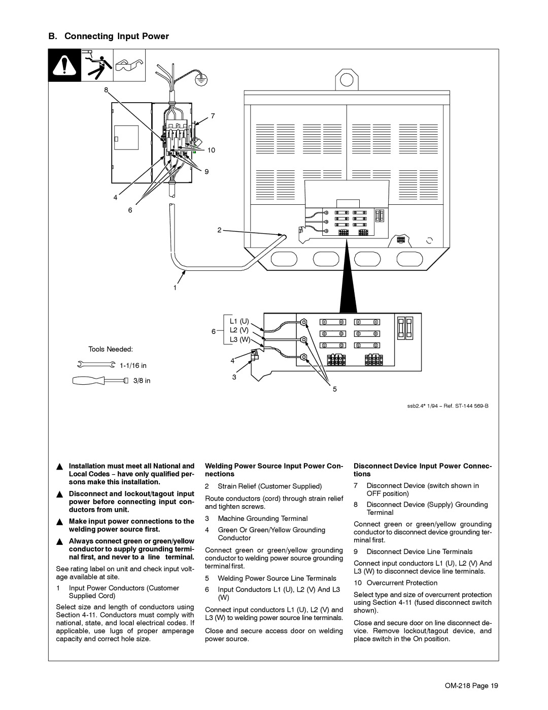
YInstallation must meet all National and Local Codes − have only qualified per- sons make this installation.
YDisconnect and lockout/tagout input power before connecting input con- ductors from unit.
YMake input power connections to the welding power source first.
YAlways connect green or green/yellow conductor to supply grounding termi-
nal first, and never to a line terminal.
See rating label on unit and check input volt- age available at site.
1Input Power Conductors (Customer Supplied Cord)
Select size and length of conductors using Section
Welding Power Source Input Power Con- nections
2 Strain Relief (Customer Supplied)
Route conductors (cord) through strain relief and tighten screws.
3Machine Grounding Terminal
4Green Or Green/Yellow Grounding Conductor
Connect green or green/yellow grounding conductor to welding power source grounding terminal first.
5Welding Power Source Line Terminals
6Input Conductors L1 (U), L2 (V) And L3
(W)
Connect input conductors L1 (U), L2 (V) and L3 (W) to welding power source line terminals.
Close and secure access door on welding power source.
Disconnect Device Input Power Connec- tions
7Disconnect Device (switch shown in OFF position)
8Disconnect Device (Supply) Grounding Terminal
Connect green or green/yellow grounding conductor to disconnect device grounding ter- minal first.
9 Disconnect Device Line Terminals
Connect input conductors L1 (U), L2 (V) And L3 (W) to disconnect device line terminals.
10 Overcurrent Protection
Select type and size of overcurrent protection using Section
Close and secure door on line disconnect de- vice. Remove lockout/tagout device, and place switch in the On position.