3-11. Placing Jumper Links And Connecting Input Power
200 VOLTS | 230 VOLTS |
| 460 VOLTS | ||||
| L | L |
| L | L | L | L |
|
|
|
|
|
| ||
230 VOLTS |
|
| 460 VOLTS | 575 VOLTS | |||
| L | L |
| L | L | L | L |
|
|
|
|
|
|
| |
220 VOLTS |
| 380 VOLTS |
| 415 VOLTS | |||
| L | L |
| L | L | L | L |
|
|
|
|
|
| ||
260 VOLTS | 380 VOLTS | 520 VOLTS | |||||
L | L |
| L | L |
| L | L |
|
|
|
|
|
| ||
1
Connect GND/PE Conductor First
Tools Needed:
3/8 in
3/8, 1/2, 7/16 in
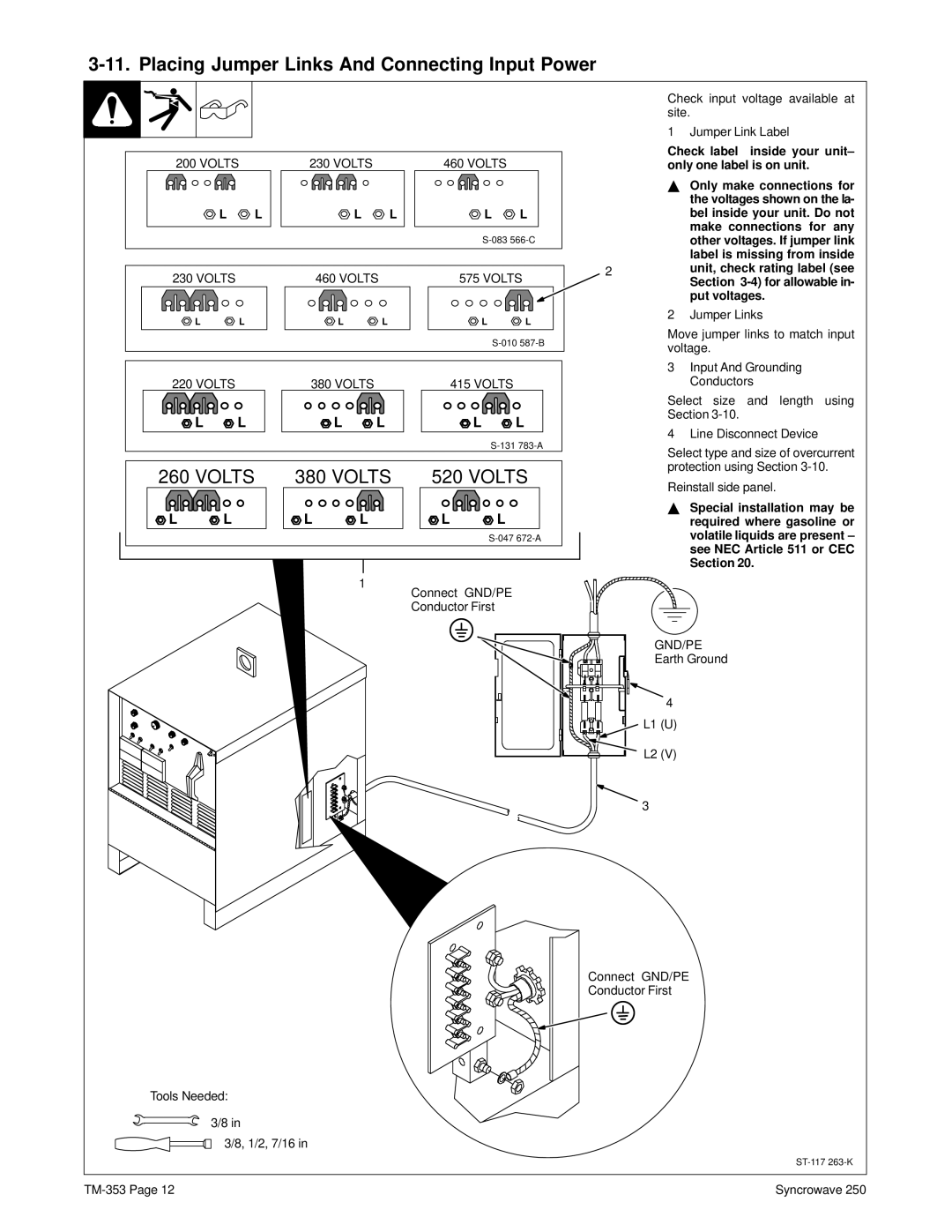
Check input voltage available at site.
1 Jumper Link Label
Check label inside your unit– only one label is on unit.
YOnly make connections for the voltages shown on the la- bel inside your unit. Do not make connections for any other voltages. If jumper link label is missing from inside
2unit, check rating label (see Section
2 Jumper Links
Move jumper links to match input voltage.
3Input And Grounding Conductors
Select size and length using
Section
4 Line Disconnect Device
Select type and size of overcurrent protection using Section
Reinstall side panel.
YSpecial installation may be required where gasoline or volatile liquids are present – see NEC Article 511 or CEC Section 20.
GND/PE
Earth Ground
4
L1 (U)
L2 (V)
3
Connect GND/PE
Conductor First
Syncrowave 250 |