3-6. Tipping
Y Be careful when placing or moving unit over uneven surfaces.
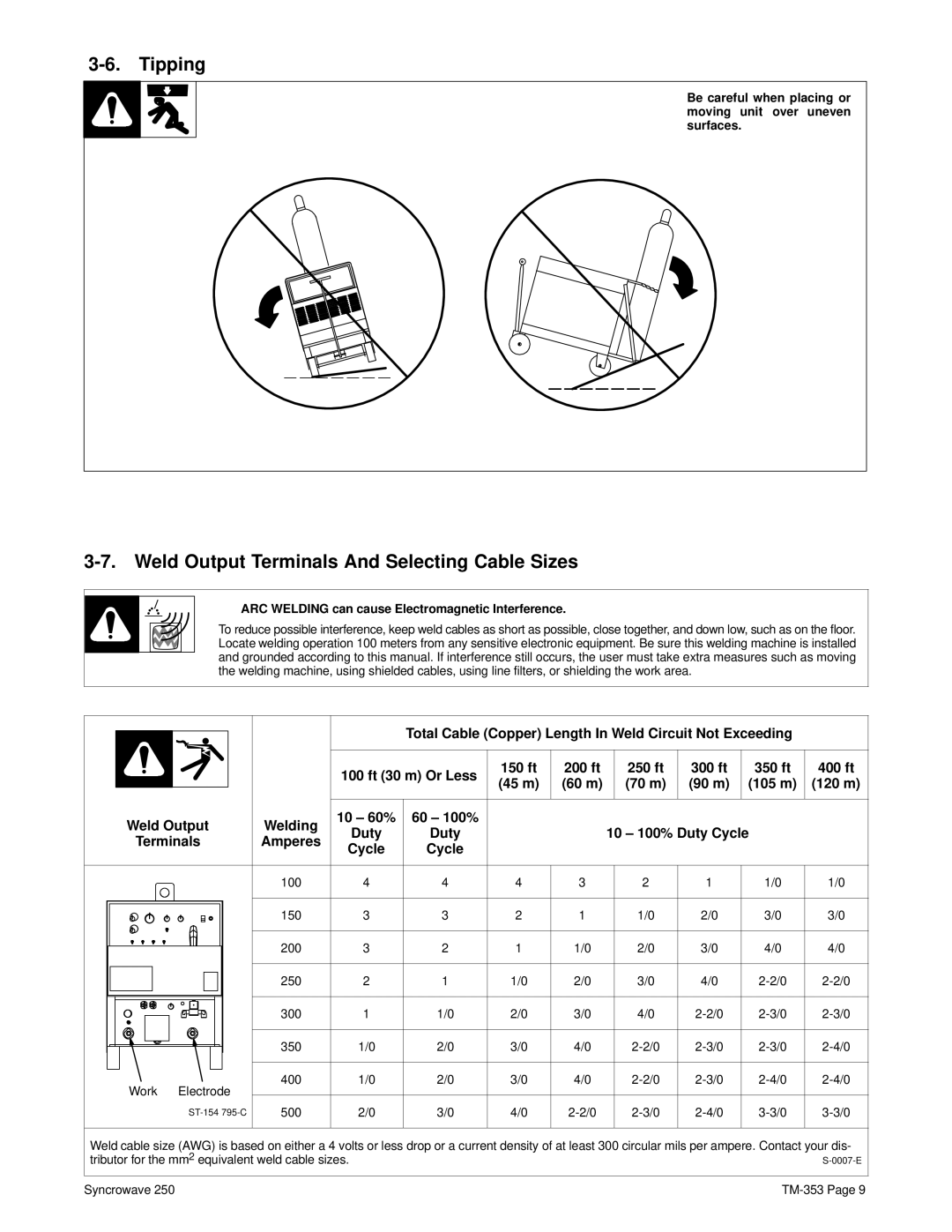
3-7. Weld Output Terminals And Selecting Cable Sizes
Y ARC WELDING can cause Electromagnetic Interference.
To reduce possible interference, keep weld cables as short as possible, close together, and down low, such as on the floor. Locate welding operation 100 meters from any sensitive electronic equipment. Be sure this welding machine is installed and grounded according to this manual. If interference still occurs, the user must take extra measures such as moving the welding machine, using shielded cables, using line filters, or shielding the work area.
|
|
| Total Cable (Copper) Length In Weld Circuit Not Exceeding |
| |||||
|
| 100 ft (30 m) Or Less | 150 ft | 200 ft | 250 ft | 300 ft | 350 ft | 400 ft | |
|
| (45 m) | (60 m) | (70 m) | (90 m) | (105 m) | (120 m) | ||
|
|
|
| ||||||
Weld Output | Welding | 10 – 60% | 60 – 100% |
|
|
|
|
|
|
Duty | Duty |
|
| 10 – 100% Duty Cycle |
| ||||
Terminals | Amperes |
|
|
| |||||
Cycle | Cycle |
|
|
|
|
|
| ||
|
|
|
|
|
|
|
| ||
| 100 | 4 | 4 | 4 | 3 | 2 | 1 | 1/0 | 1/0 |
| 150 | 3 | 3 | 2 | 1 | 1/0 | 2/0 | 3/0 | 3/0 |
| 200 | 3 | 2 | 1 | 1/0 | 2/0 | 3/0 | 4/0 | 4/0 |
| 250 | 2 | 1 | 1/0 | 2/0 | 3/0 | 4/0 | ||
| 300 | 1 | 1/0 | 2/0 | 3/0 | 4/0 | |||
| 350 | 1/0 | 2/0 | 3/0 | 4/0 | ||||
Work Electrode | 400 | 1/0 | 2/0 | 3/0 | 4/0 | ||||
|
|
|
|
|
|
|
|
| |
500 | 2/0 | 3/0 | 4/0 | ||||||
Weld cable size (AWG) is based on either a 4 volts or less drop or a current density of at least 300 circular mils per ampere. Contact your dis- tributor for the mm2 equivalent weld cable sizes.
Syncrowave 250