Contents
SyncrowaveR
Table of Contents
Declaration of Conformity For European Community CE Products
Page
Servicing Hazards
Safety Precautions for Servicing
Symbol Usage
Marks a special safety message
About Pacemakers
EMF Information
Definitions
+ + +
Rating Label For CE Products
ISO/IEC
Some symbols are found only on CE products
Symbols And Definitions
220 230 260 380 415 460
Installation
Specifications
Volt-Ampere Curves
60% Duty Cycle At 200 Amperes
Duty Cycle And Overheating
Overheating
Selecting a Location
Dimensions And Weights
Movement Location And Airflow
ARC Welding can cause Electromagnetic Interference
Be careful when placing or moving unit over uneven surfaces
Tipping
Weld Output Terminals And Selecting Cable Sizes
Socket
Turn Off power before connecting to receptacle
Remote 14 Receptacle
Volts AC Duplex Receptacle And Shielding Gas Connections
All values calculated at 60% duty cycle
Electrical Service Guide
Check label inside your unit- only one label is on unit
Placing Jumper Links And Connecting Input Power
Controls
Operation
Meters
Output Selector Switch
Spot Time Controls
Crater Time Controls
Application
AC Balance Control
Setting Output Waveforms
Balance Control AC Gtaw
Output Contactor Control Switch
Amperage Adjustment Controls
Postflow Time Control
Arc Controls
For AC And DC Smaw Welding
Preflow Time Control Optional
High Frequency Controls
SCR
Theory of Operation
HD1
Troubleshooting Table
Troubleshooting
Necessary parts
Dition of contacts. Replace CR5 if necessary
Contacts. Replace CR2 if necessary
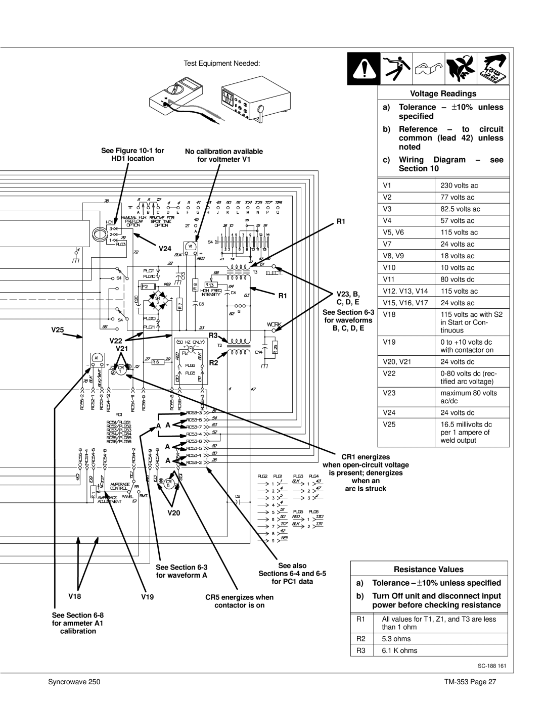
Troubleshooting Circuit Diagram For Welding Power Source
D, E
See -1 for
HD1 location
V24
Gnd
Waveforms For Section
AC Output, 100 Amperes, 24 Volts AC Re- sistive Load
Control Board PC1 Testing Information Use With Section
Reference for gate pulse to SCR4 RC54 Not used
Control Board PC1 Test Point Values
Receptacle Pin Value
Remote Board PC2 Testing Information Use With Section
RC3
Meter Calibration
Input Voltage Labels And Connections
Circuit Breaker CB1
Maintenance
Routine Maintenance
Months
Turn Off power before adjusting spark gaps
Adjusting Spark Gaps
Fuses F1 And F2
Sources Of HF Radiation From Incorrect Installation
Welding Processes Using HF
High Frequency HF
Correct Installation
Model Serial Or Style Number Circuit Diagram Wiring Diagram
Electrical Diagrams
SC-114
SC-120
SC-121
SC-124
SC-124 785-B
SC-132 697-A
SC-137
SC-135
SC-142
SC-148
SC-154 649-C
SC-178
SC-179 303-A
SC-181 109-E
SC-188 161-A
Syncrowave TM-353
TM-353
SD-188 162-A
TM-353
SD-187 644 1
TM-353
SD-187 644 2
SA-121
SA-044 725-C
TM-353
Description
Main Assembly
Parts List
PLG51
114 BASE, Prior to KE727074 170
Panel, Front w/Components
Panel, Front w/ Components
Rectifier, Si Diode -1 Item
Panel, Mtg Components -1 Item
Control Panel, Lower Front
126 Capacitor ASSEMBLY, Eff w/JK537589 thru JK690986 C14
124 COIL, HF coupling Eff w/JK572898 thru KF959378 174
Optional Equipment
Page
Miller