| 26 | 28 |
|
|
|
|
|
|
| 30 | |
25 |
|
|
|
| |
Hall Device |
|
|
| Work Weld | |
|
|
|
| ||
Stabilizer | HD1 |
|
|
| Output |
|
| 11♦ |
| Terminal | |
Z1 |
|
|
| ||
|
|
|
| ||
|
| Output | Voltmeter |
|
|
|
| V1 |
|
| |
|
| Selector |
|
| |
|
|
|
|
| |
|
| Switch |
|
| 30 |
|
| S4 | 21 |
| Electrode |
|
|
|
|
| |
|
|
|
|
| Weld Output |
|
|
|
| High | Terminal |
|
|
|
| Frequency |
|
|
|
|
| Coupling |
|
|
|
|
| Coil T3 |
|
| 27 | 29 | 22 |
|
|
| Line |
|
| Integrated | High |
| |||||
|
|
| Frequency |
| |||||||
| Filter |
|
| Rectifier |
| ||||||
|
|
| Intensity |
| |||||||
| FL1 |
|
| SR2 |
| ||||||
|
|
| Control R13 |
| |||||||
|
|
|
|
|
|
|
|
|
| ||
|
|
|
|
|
|
|
|
|
|
|
|
Current Feedback |
|
|
|
|
|
|
| 21 |
|
| |
|
|
| Voltage Feedback |
|
|
|
| Spark Gaps G |
| ||
|
|
|
|
|
|
| Capacitor |
| |||
|
|
|
|
|
|
|
|
|
| ||
|
|
| Voltage Feedback |
|
|
|
| C4 |
| ||
|
|
|
|
|
|
|
|
|
| ||
20
High
Frequency
Transformer
T2
115 VAC
18♦ |
| 19♦ | ||
Preflow |
| Spot | ||
Timer |
| Timer | ||
| ||||
TD3 |
| TD2 | ||
|
|
|
|
|
18♦ |
| 19♦ |
| |
Preflow Time |
| Spot Time | ||
Control |
| Control | ||
R12 |
| R10 | ||
|
|
|
|
|
Switch |
|
|
| |
S9 | 19♦ |
| ||
|
|
| Spot Time | |
|
|
| Switch | |
|
|
| S8 | |
|
|
|
|
|
AC Or DC Control
1φ Power
Weld Current Circuit
External Circuits
♦Optional
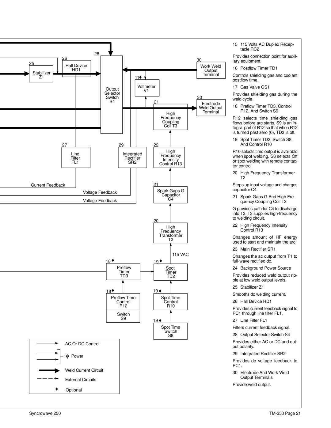
15115 Volts AC Duplex Recep- tacle RC2
Provides connection point for auxil- iary equipment.
16 Postflow Timer TD1
Controls shielding gas and coolant postflow time.
17 Gas Valve GS1
Provides shielding gas during the weld cycle.
18Preflow Timer TD3, Control R12, And Switch S9
R12 selects time shielding gas flows before arc starts. S9 is an in- tegral part of R12 so that when R12 is turned past zero (0), TD3 is off.
19Spot Timer TD2, Switch S8, And Control R10
R10 selects time output is available when spot welding. S8 selects Off or spot welding with remote contac- tor control.
20High Frequency Transformer T2
Steps up input voltage and charges capacitor C4.
21Spark Gaps G And High Fre- quency Coupling Coil T3
G provides path for C4 to discharge into T3. T3 supplies
22High Frequency Intensity Control R13
Changes amount of HF energy used to start and maintain the arc.
23 Main Rectifier SR1
Changes the ac output from T1 to
24 Background Power Source
Provides reduced weld output rip- ple at low weld output levels.
25 Stabilizer Z1
Smooths dc welding current.
26 Hall Device HD1
Provides current feedback signal to PC1 through line filter FL1.
27 Line Filter FL1
Filters current feedback signal.
28 Output Selector Switch S4
Provides either AC or DC and out- put polarity.
29 Integrated Rectifier SR2
Provides dc voltage feedback to PC1.
30Electrode And Work Weld Output Terminals
Provide weld output.
Syncrowave 250 |