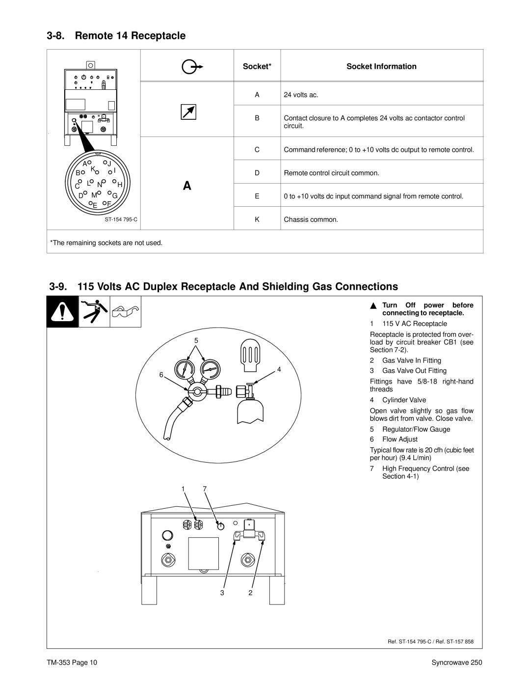
3-8. Remote 14 Receptacle
A | J | |
B | K | I |
|
| |
C | L N | H |
D | M | G |
| E | F |
|
|
| Socket* | Socket Information |
|
|
|
|
|
|
|
|
|
|
|
|
| A | 24 volts ac. |
|
|
|
|
|
|
|
| B | Contact closure to A completes 24 volts ac contactor control |
|
| |||
|
|
|
| circuit. |
CCommand reference; 0 to +10 volts dc output to remote control.
DRemote control circuit common.
A
E0 to +10 volts dc input command signal from remote control.
K Chassis common.
*The remaining sockets are not used.
3-9. 115 Volts AC Duplex Receptacle And Shielding Gas Connections
Y Turn Off power before connecting to receptacle.
1 115 V AC Receptacle
Receptacle is protected from over-
5load by circuit breaker CB1 (see Section
|
| 2 | Gas Valve In Fitting |
6 | 4 | 3 | Gas Valve Out Fitting |
| Fittings have | ||
|
| ||
|
| threads | |
|
| 4 | Cylinder Valve |
|
| Open valve slightly so gas flow | |
|
| blows dirt from valve. Close valve. | |
|
| 5 | Regulator/Flow Gauge |
|
| 6 | Flow Adjust |
|
| Typical flow rate is 20 cfh (cubic feet | |
|
| per hour) (9.4 L/min) | |
|
| 7 | High Frequency Control (see |
|
|
| Section |
1 | 7 |
|
|
3 2
Ref.
Syncrowave 250 |
