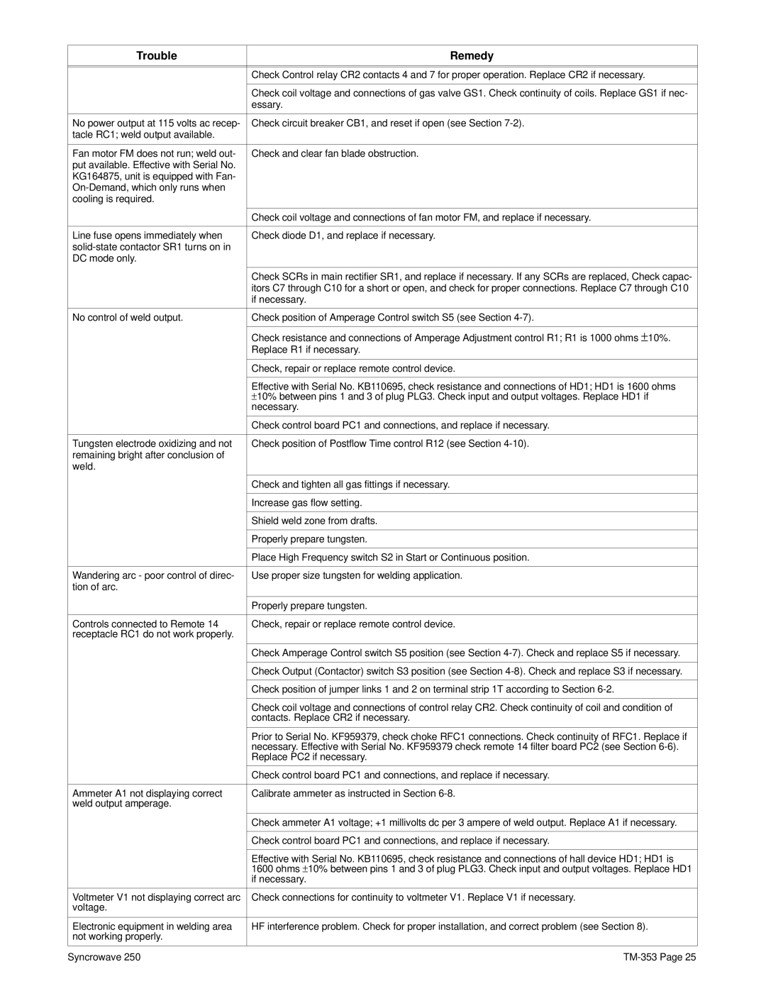
Trouble | Remedy |
|
|
|
|
| Check Control relay CR2 contacts 4 and 7 for proper operation. Replace CR2 if necessary. |
|
|
| Check coil voltage and connections of gas valve GS1. Check continuity of coils. Replace GS1 if nec- |
| essary. |
|
|
No power output at 115 volts ac recep- | Check circuit breaker CB1, and reset if open (see Section |
tacle RC1; weld output available. |
|
|
|
Fan motor FM does not run; weld out- | Check and clear fan blade obstruction. |
put available. Effective with Serial No. |
|
KG164875, unit is equipped with Fan- |
|
| |
cooling is required. |
|
|
|
| Check coil voltage and connections of fan motor FM, and replace if necessary. |
|
|
Line fuse opens immediately when | Check diode D1, and replace if necessary. |
| |
DC mode only. |
|
|
|
| Check SCRs in main rectifier SR1, and replace if necessary. If any SCRs are replaced, Check capac- |
| itors C7 through C10 for a short or open, and check for proper connections. Replace C7 through C10 |
| if necessary. |
|
|
No control of weld output. | Check position of Amperage Control switch S5 (see Section |
|
|
| Check resistance and connections of Amperage Adjustment control R1; R1 is 1000 ohms ± 10%. |
| Replace R1 if necessary. |
|
|
| Check, repair or replace remote control device. |
|
|
| Effective with Serial No. KB110695, check resistance and connections of HD1; HD1 is 1600 ohms |
| ± 10% between pins 1 and 3 of plug PLG3. Check input and output voltages. Replace HD1 if |
| necessary. |
|
|
| Check control board PC1 and connections, and replace if necessary. |
|
|
Tungsten electrode oxidizing and not | Check position of Postflow Time control R12 (see Section |
remaining bright after conclusion of |
|
weld. |
|
|
|
| Check and tighten all gas fittings if necessary. |
|
|
| Increase gas flow setting. |
|
|
| Shield weld zone from drafts. |
|
|
| Properly prepare tungsten. |
|
|
| Place High Frequency switch S2 in Start or Continuous position. |
|
|
Wandering arc - poor control of direc- | Use proper size tungsten for welding application. |
tion of arc. |
|
|
|
| Properly prepare tungsten. |
|
|
Controls connected to Remote 14 | Check, repair or replace remote control device. |
receptacle RC1 do not work properly. |
|
|
|
| Check Amperage Control switch S5 position (see Section |
|
|
| Check Output (Contactor) switch S3 position (see Section |
|
|
| Check position of jumper links 1 and 2 on terminal strip 1T according to Section |
|
|
| Check coil voltage and connections of control relay CR2. Check continuity of coil and condition of |
| contacts. Replace CR2 if necessary. |
|
|
| Prior to Serial No. KF959379, check choke RFC1 connections. Check continuity of RFC1. Replace if |
| necessary. Effective with Serial No. KF959379 check remote 14 filter board PC2 (see Section |
| Replace PC2 if necessary. |
|
|
| Check control board PC1 and connections, and replace if necessary. |
|
|
Ammeter A1 not displaying correct | Calibrate ammeter as instructed in Section |
weld output amperage. |
|
|
|
| Check ammeter A1 voltage; +1 millivolts dc per 3 ampere of weld output. Replace A1 if necessary. |
|
|
| Check control board PC1 and connections, and replace if necessary. |
|
|
| Effective with Serial No. KB110695, check resistance and connections of hall device HD1; HD1 is |
| 1600 ohms ± 10% between pins 1 and 3 of plug PLG3. Check input and output voltages. Replace HD1 |
| if necessary. |
|
|
Voltmeter V1 not displaying correct arc | Check connections for continuity to voltmeter V1. Replace V1 if necessary. |
voltage. |
|
|
|
Electronic equipment in welding area | HF interference problem. Check for proper installation, and correct problem (see Section 8). |
not working properly. |
|
|
|
Syncrowave 250 |