INSTALLATION AND WIRING
(2) Terminal block layout
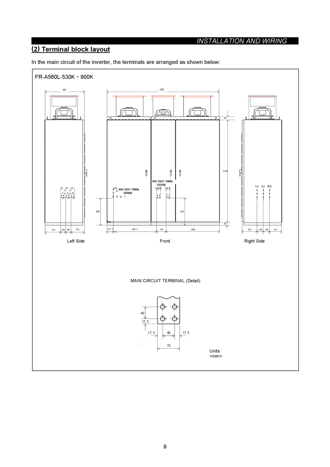
In the main circuit of the inverter, the terminals are arranged as shown below:
Left Side | Front | Right Side |
MAIN CIRCUIT TERMINAL (Detail)
40
17.5
17.5 40 17.5
75
Units <mm>
9
INSTALLATION AND WIRING
In the main circuit of the inverter, the terminals are arranged as shown below:
Left Side | Front | Right Side |
MAIN CIRCUIT TERMINAL (Detail)
40
17.5
17.5 40 17.5
75
Units <mm>
9