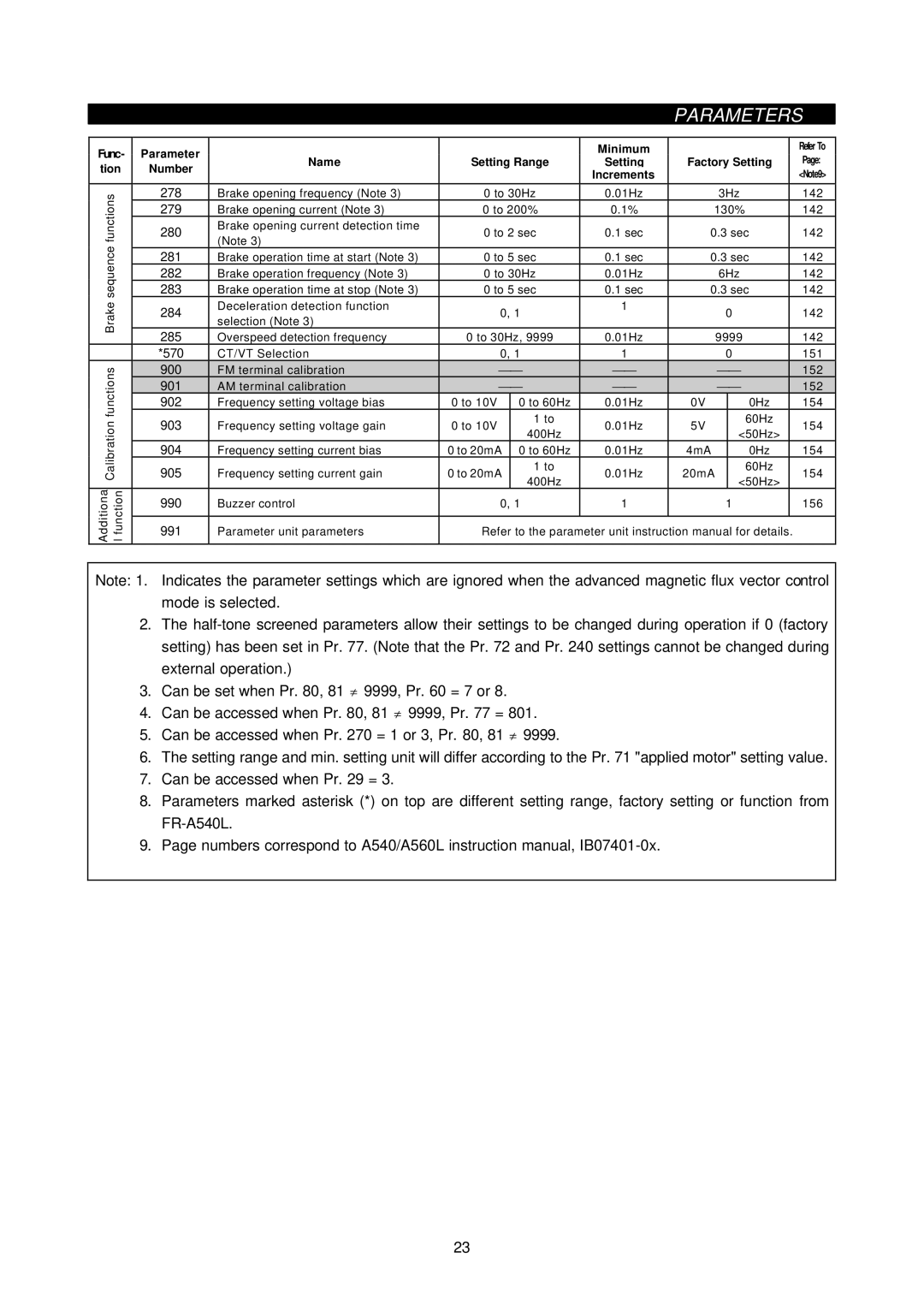
PARAMETERS
Func- | Parameter |
|
|
| Minimum |
|
|
|
|
| Refer To |
Name | Setting Range | Setting | Factory Setting |
| Page: | ||||||
tion | Number |
| |||||||||
|
|
| Increments |
|
|
|
|
| <Note9> | ||
|
|
|
|
|
|
|
|
|
| ||
|
|
|
|
|
|
|
|
|
|
|
|
functions | 278 | Brake opening frequency (Note 3) | 0 to 30Hz | 0.01Hz |
|
| 3Hz |
| 142 | ||
279 | Brake opening current (Note 3) | 0 to 200% | 0.1% |
| 130% |
| 142 | ||||
|
|
| |||||||||
| 280 | Brake opening current detection time | 0 to 2 sec | 0.1 sec | 0.3 sec |
| 142 | ||||
| (Note 3) |
| |||||||||
sequence |
|
|
|
|
|
|
|
|
|
| |
283 | Brake operation time at stop (Note 3) | 0 to 5 sec | 0.1 sec | 0.3 sec |
| 142 | |||||
| 281 | Brake operation time at start (Note 3) | 0 to 5 sec | 0.1 sec | 0.3 sec |
| 142 | ||||
| 282 | Brake operation frequency (Note 3) | 0 to 30Hz | 0.01Hz |
|
| 6Hz |
| 142 | ||
|
|
|
|
|
|
|
|
|
|
|
|
Brake | 284 | Deceleration detection function | 0, 1 | 1 |
|
| 0 |
| 142 | ||
selection (Note 3) |
|
|
|
| |||||||
|
|
|
|
| |||||||
|
|
|
|
|
|
|
|
|
|
| |
| 285 | Overspeed detection frequency | 0 to 30Hz, 9999 | 0.01Hz |
|
| 9999 |
| 142 | ||
| *570 | CT/VT Selection | 0, 1 | 1 |
|
| 0 |
| 151 | ||
functions | 900 | FM terminal calibration | ⎯⎯ | ⎯⎯ |
|
| ⎯⎯ |
| 152 | ||
901 | AM terminal calibration | ⎯⎯ | ⎯⎯ |
|
| ⎯⎯ |
| 152 | |||
| 902 | Frequency setting voltage bias | 0 to 10V | 0 to 60Hz | 0.01Hz | 0V |
|
| 0Hz |
| 154 |
Calibration | 903 | Frequency setting voltage gain | 0 to 10V | 1 to | 0.01Hz | 5V |
|
| 60Hz |
| 154 |
400Hz |
|
| <50Hz> |
| |||||||
905 | Frequency setting current gain | 0 to 20mA | 0.01Hz | 20mA |
|
| 154 | ||||
|
|
|
|
|
|
|
|
|
| ||
| 904 | Frequency setting current bias | 0 to 20mA | 0 to 60Hz | 0.01Hz | 4mA |
|
| 0Hz |
| 154 |
|
|
|
| 1 to |
|
|
|
| 60Hz |
|
|
|
|
|
| 400Hz |
|
|
|
| <50Hz> |
|
|
Additiona functionl | 990 | Buzzer control | 0, 1 | 1 |
|
| 1 |
| 156 | ||
|
|
|
| ||||||||
|
|
|
|
|
|
|
| ||||
| 991 | Parameter unit parameters | Refer to the parameter unit instruction manual for details. |
| |||||||
|
|
|
|
|
|
|
|
|
|
|
|
Note: 1. Indicates the parameter settings which are ignored when the advanced magnetic flux vector control mode is selected.
2.The
3.Can be set when Pr. 80, 81 ≠ 9999, Pr. 60 = 7 or 8.
4.Can be accessed when Pr. 80, 81 ≠ 9999, Pr. 77 = 801.
5.Can be accessed when Pr. 270 = 1 or 3, Pr. 80, 81 ≠ 9999.
6.The setting range and min. setting unit will differ according to the Pr. 71 "applied motor" setting value.
7.Can be accessed when Pr. 29 = 3.
8.Parameters marked asterisk (*) on top are different setting range, factory setting or function from
9.Page numbers correspond to A540/A560L instruction manual,
23