PROTECTIVE FUNCTIONS
zChecking the inverter and converter modules
<Preparation>
(1)Disconnect the external power supply cables (R, S, T) <L1, L2, L3> and motor cables (U, V, W).
(2)Prepare a tester. (Use 100Ω range.)
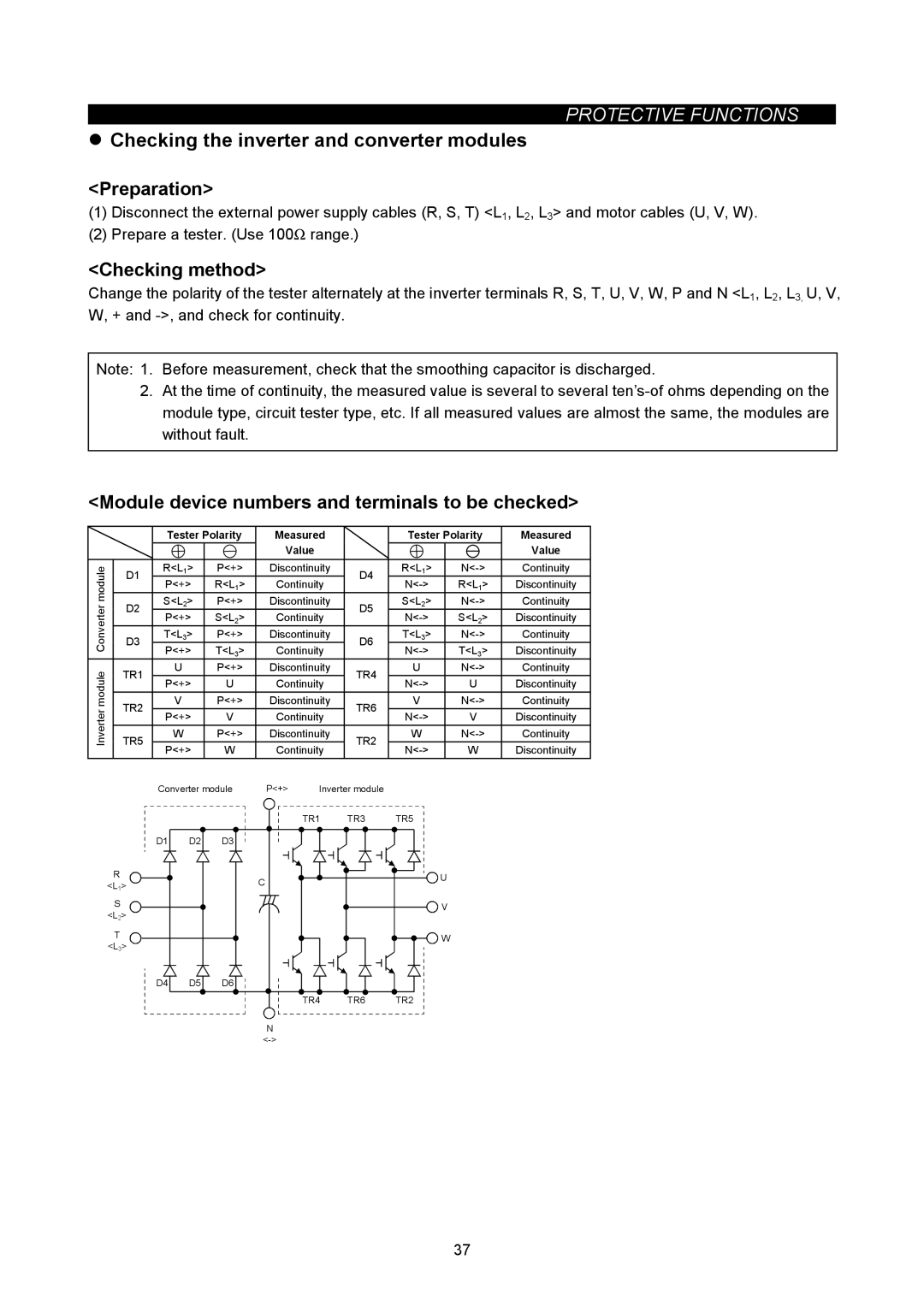
<Checking method>
Change the polarity of the tester alternately at the inverter terminals R, S, T, U, V, W, P and N <L1, L2, L3, U, V, W, + and
Note: 1. Before measurement, check that the smoothing capacitor is discharged.
2.At the time of continuity, the measured value is several to several
<Module device numbers and terminals to be checked>
|
| Tester Polarity | Measured |
| Tester Polarity | Measured | |||||
|
|
|
|
| Value |
|
|
| Value | ||
module | D1 | R<L1> | P<+> | Discontinuity | D4 | R<L1> | Continuity | ||||
P<+> | R<L1> | Continuity | R<L1> | Discontinuity | |||||||
|
| ||||||||||
D2 | S<L2> | P<+> | Discontinuity | D5 | S<L2> | Continuity | |||||
Converter | |||||||||||
P<+> | S<L2> | Continuity | S<L2> | Discontinuity | |||||||
|
| ||||||||||
D3 | T<L3> | P<+> | Discontinuity | D6 | T<L3> | Continuity | |||||
P<+> | T<L3> | Continuity | T<L3> | Discontinuity | |||||||
|
| ||||||||||
|
|
| |||||||||
module | TR1 |
| U | P<+> | Discontinuity | TR4 | U | Continuity | |||
P<+> | U | Continuity | U | Discontinuity | |||||||
|
| ||||||||||
TR2 |
| V | P<+> | Discontinuity | TR6 | V | Continuity | ||||
Inverter | P<+> | V | Continuity | V | Discontinuity | ||||||
|
| ||||||||||
TR5 |
| W | P<+> | Discontinuity | TR2 | W | Continuity | ||||
P<+> | W | Continuity | W | Discontinuity | |||||||
|
|
| |||||||||
|
| Converter module | P<+> | Inverter module |
|
|
| ||||
|
|
|
|
|
| TR1 | TR3 | TR5 |
|
| |
|
| D1 | D2 | D3 |
|
|
|
|
|
| |
| R |
|
|
| C |
|
|
| U |
| |
| <L1> |
|
|
|
|
|
|
| |||
|
|
|
|
|
|
|
|
| |||
|
|
|
|
|
|
|
|
|
| ||
| S |
|
|
|
|
|
|
| V |
| |
| <L2> |
|
|
|
|
|
|
|
| ||
|
|
|
|
|
|
|
|
|
| ||
| T |
|
|
|
|
|
|
| W |
| |
| <L3> |
|
|
|
|
|
|
|
| ||
|
|
|
|
|
|
|
|
|
| ||
|
| D4 | D5 | D6 |
|
|
|
|
|
| |
|
|
|
|
|
| TR4 | TR6 | TR2 |
|
| |
|
|
|
|
| N |
|
|
|
|
| |
|
|
|
|
|
|
|
|
|
| ||
37