|
|
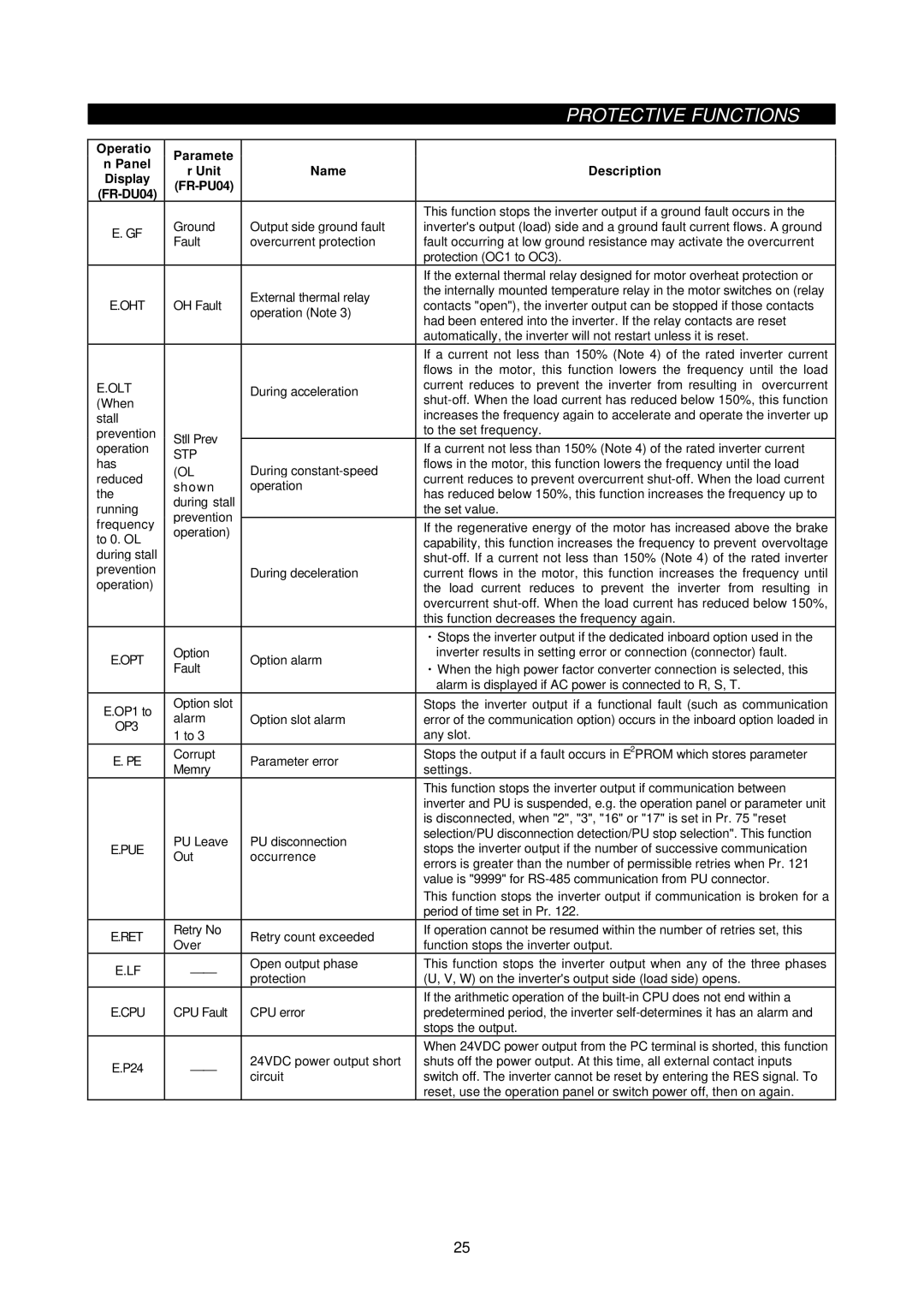
| PROTECTIVE FUNCTIONS | |
|
|
|
| |
Operatio | Paramete |
|
| |
n Panel |
|
| ||
r Unit | Name | Description | ||
Display | ||||
|
| |||
|
| |||
|
|
| ||
|
|
| This function stops the inverter output if a ground fault occurs in the | |
E. GF | Ground | Output side ground fault | inverter's output (load) side and a ground fault current flows. A ground | |
Fault | overcurrent protection | fault occurring at low ground resistance may activate the overcurrent | ||
| ||||
|
|
| protection (OC1 to OC3). | |
|
|
| If the external thermal relay designed for motor overheat protection or | |
|
| External thermal relay | the internally mounted temperature relay in the motor switches on (relay | |
E.OHT | OH Fault | contacts "open"), the inverter output can be stopped if those contacts | ||
operation (Note 3) | ||||
|
| had been entered into the inverter. If the relay contacts are reset | ||
|
|
| ||
|
|
| automatically, the inverter will not restart unless it is reset. | |
|
|
| If a current not less than 150% (Note 4) of the rated inverter current | |
|
|
| flows in the motor, this function lowers the frequency until the load | |
E.OLT |
| During acceleration | current reduces to prevent the inverter from resulting in overcurrent | |
(When |
|
| ||
stall |
|
| increases the frequency again to accelerate and operate the inverter up | |
prevention | Stll Prev |
| to the set frequency. | |
operation |
| If a current not less than 150% (Note 4) of the rated inverter current | ||
STP |
| |||
has |
| flows in the motor, this function lowers the frequency until the load | ||
(OL | During | |||
reduced | current reduces to prevent overcurrent | |||
shown | operation | |||
the | has reduced below 150%, this function increases the frequency up to | |||
during stall |
| |||
running |
| the set value. | ||
prevention |
| |||
frequency |
| If the regenerative energy of the motor has increased above the brake | ||
operation) |
| |||
to 0. OL |
| capability, this function increases the frequency to prevent overvoltage | ||
|
| |||
during stall |
|
| ||
prevention |
| During deceleration | current flows in the motor, this function increases the frequency until | |
operation) |
|
| the load current reduces to prevent the inverter from resulting in | |
|
|
| overcurrent | |
|
|
| this function decreases the frequency again. | |
|
|
| ・Stops the inverter output if the dedicated inboard option used in the | |
E.OPT | Option | Option alarm | inverter results in setting error or connection (connector) fault. | |
Fault | ・When the high power factor converter connection is selected, this | |||
|
| |||
|
|
| alarm is displayed if AC power is connected to R, S, T. | |
E.OP1 to | Option slot |
| Stops the inverter output if a functional fault (such as communication | |
alarm | Option slot alarm | error of the communication option) occurs in the inboard option loaded in | ||
OP3 | ||||
1 to 3 |
| any slot. | ||
|
| |||
E. PE | Corrupt | Parameter error | Stops the output if a fault occurs in E2PROM which stores parameter | |
Memry | settings. | |||
|
| |||
|
|
| This function stops the inverter output if communication between | |
|
|
| inverter and PU is suspended, e.g. the operation panel or parameter unit | |
|
|
| is disconnected, when "2", "3", "16" or "17" is set in Pr. 75 "reset | |
| PU Leave | PU disconnection | selection/PU disconnection detection/PU stop selection". This function | |
E.PUE | stops the inverter output if the number of successive communication | |||
Out | occurrence | |||
| errors is greater than the number of permissible retries when Pr. 121 | |||
|
|
| ||
|
|
| value is "9999" for | |
|
|
| This function stops the inverter output if communication is broken for a | |
|
|
| period of time set in Pr. 122. | |
E.RET | Retry No | Retry count exceeded | If operation cannot be resumed within the number of retries set, this | |
Over | function stops the inverter output. | |||
|
| |||
E.LF | ⎯⎯ | Open output phase | This function stops the inverter output when any of the three phases | |
protection | (U, V, W) on the inverter's output side (load side) opens. | |||
|
| |||
|
|
| If the arithmetic operation of the | |
E.CPU | CPU Fault | CPU error | predetermined period, the inverter | |
|
|
| stops the output. | |
|
|
| When 24VDC power output from the PC terminal is shorted, this function | |
E.P24 | ⎯⎯ | 24VDC power output short | shuts off the power output. At this time, all external contact inputs | |
circuit | switch off. The inverter cannot be reset by entering the RES signal. To | |||
|
| |||
|
|
| reset, use the operation panel or switch power off, then on again. |
25