INSTALLATION AND WIRING
5)Source logic type
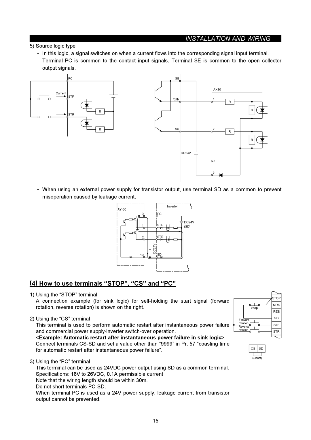
•In this logic, a signal switches on when a current flows into the corresponding signal input terminal. Terminal PC is common to the contact input signals. Terminal SE is common to the open collector output signals.
PC |
Current |
STF |
R |
STR |
R |
SE |
|
| AX80 |
RUN | 1 |
| R |
| R |
SU | 2 |
| R |
| R |
| DC24V |
| 8 |
| 9 |
•When using an external power supply for transistor output, use terminal SD as a common to prevent misoperation caused by leakage current.
|
| Inverter | |
|
|
| |
9 |
| PC |
|
1 |
| STF | DC24V |
| (SD) | ||
2 |
| STR |
|
10 | DC24V | SD |
|
|
|
(4) How to use terminals “STOP”, “CS” and “PC”
1)Using the “STOP” terminal
A connection example (for sink logic) for
2)Using the “CS” terminal
This terminal is used to perform automatic restart after instantaneous power failure and commercial power
<Example: Automatic restart after instantaneous power failure in sink logic> Connect terminals
3)Using the “PC” terminal
This terminal can be used as 24VDC power output using SD as a common terminal. Specifications: 18V to 26VDC, 0.1A permissible current
Note that the wiring length should be within 30m. Do not short terminals
When terminal PC is used as a 24V power supply, leakage current from transistor output cannot be prevented.
| STOP | |
| MRS | |
| Stop | |
| RES | |
Forward | SD | |
| ||
rotation | STF | |
Reverse | ||
| ||
rotation | STR | |
|
CS SD
(Short)
15