|
|
| PROTECTIVE FUNCTIONS | |
|
|
|
| |
Operatio | Paramete |
|
| |
n Panel |
|
| ||
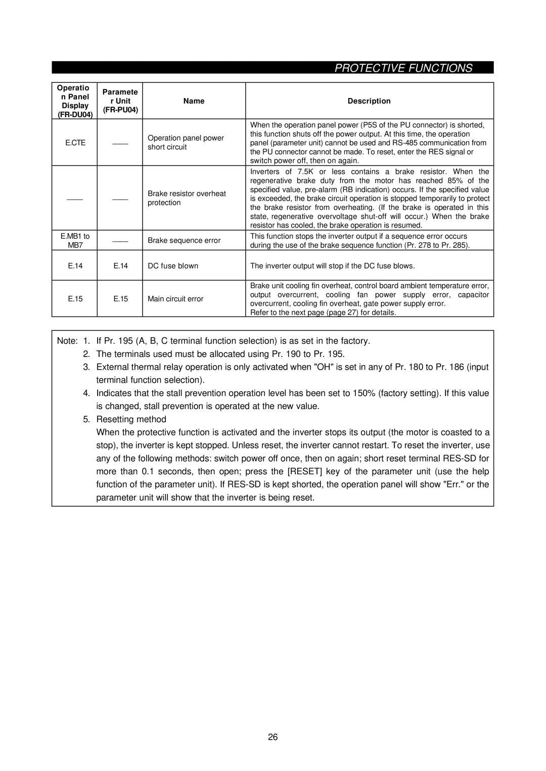
r Unit | Name | Description | ||
Display | ||||
|
|
| ||
|
|
| ||
|
|
| ||
|
|
| When the operation panel power (P5S of the PU connector) is shorted, | |
|
| Operation panel power | this function shuts off the power output. At this time, the operation | |
E.CTE | ⎯⎯ | panel (parameter unit) cannot be used and | ||
short circuit | ||||
|
| the PU connector cannot be made. To reset, enter the RES signal or | ||
|
|
| ||
|
|
| switch power off, then on again. | |
|
|
| Inverters of 7.5K or less contains a brake resistor. When the | |
|
|
| regenerative brake duty from the motor has reached 85% of the | |
|
| Brake resistor overheat | specified value, | |
⎯⎯ | ⎯⎯ | is exceeded, the brake circuit operation is stopped temporarily to protect | ||
protection | ||||
|
| the brake resistor from overheating. (If the brake is operated in this | ||
|
|
| ||
|
|
| state, regenerative overvoltage | |
|
|
| resistor has cooled, the brake operation is resumed. | |
E.MB1 to | ⎯⎯ | Brake sequence error | This function stops the inverter output if a sequence error occurs | |
MB7 | during the use of the brake sequence function (Pr. 278 to Pr. 285). | |||
|
| |||
E.14 | E.14 | DC fuse blown | The inverter output will stop if the DC fuse blows. | |
|
|
|
| |
|
|
| Brake unit cooling fin overheat, control board ambient temperature error, | |
E.15 | E.15 | Main circuit error | output overcurrent, cooling fan power supply error, capacitor | |
overcurrent, cooling fin overheat, gate power supply error. | ||||
|
|
| ||
|
|
| Refer to the next page (page 27) for details. |
Note: 1. If Pr. 195 (A, B, C terminal function selection) is as set in the factory.
2. The terminals used must be allocated using Pr. 190 to Pr. 195.
3. External thermal relay operation is only activated when "OH" is set in any of Pr. 180 to Pr. 186 (input terminal function selection).
4. Indicates that the stall prevention operation level has been set to 150% (factory setting). If this value is changed, stall prevention is operated at the new value.
5. Resetting method
When the protective function is activated and the inverter stops its output (the motor is coasted to a stop), the inverter is kept stopped. Unless reset, the inverter cannot restart. To reset the inverter, use any of the following methods: switch power off once, then on again; short reset terminal
26