| Rev. 1 | ||
SNMP Interface |
| CD/CIM25600L.IOM | |
|
|
| |
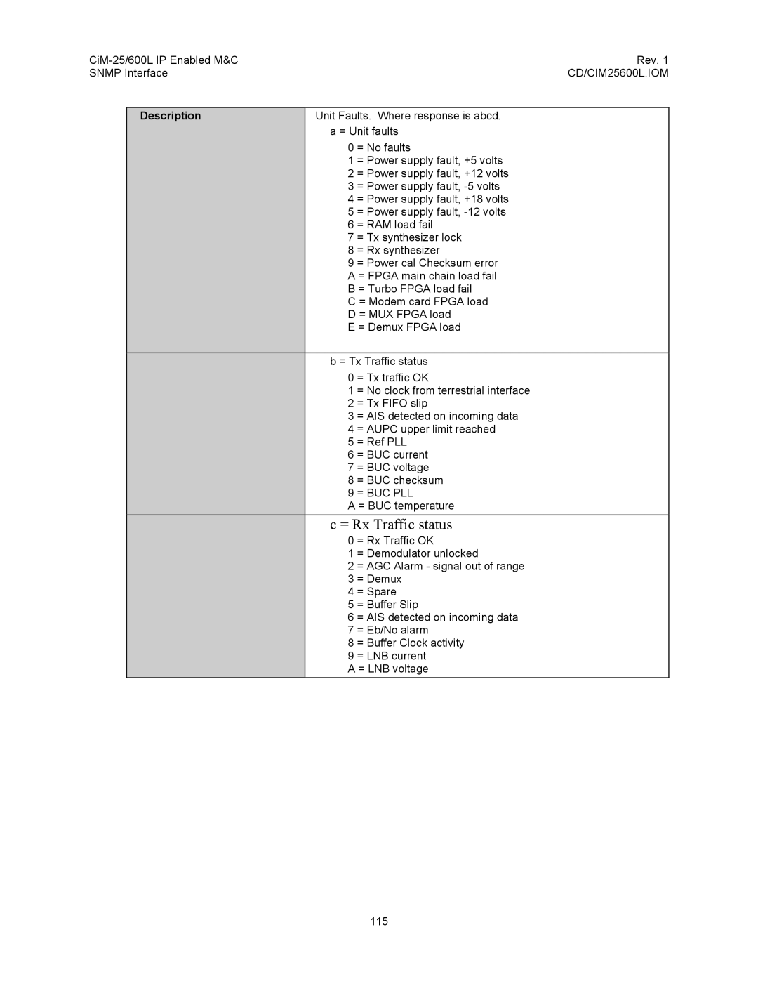
| Description | Unit Faults. Where response is abcd. | |
|
| a = Unit faults | |
|
| 0 | = No faults |
|
| 1 | = Power supply fault, +5 volts |
|
| 2 | = Power supply fault, +12 volts |
|
| 3 | = Power supply fault, |
|
| 4 | = Power supply fault, +18 volts |
|
| 5 | = Power supply fault, |
|
| 6 | = RAM load fail |
|
| 7 | = Tx synthesizer lock |
|
| 8 | = Rx synthesizer |
|
| 9 | = Power cal Checksum error |
|
| A = FPGA main chain load fail | |
|
| B = Turbo FPGA load fail | |
|
| C = Modem card FPGA load | |
|
| D = MUX FPGA load | |
|
| E = Demux FPGA load | |
|
|
| |
|
| b = Tx Traffic status | |
|
| 0 | = Tx traffic OK |
|
| 1 | = No clock from terrestrial interface |
|
| 2 | = Tx FIFO slip |
|
| 3 | = AIS detected on incoming data |
|
| 4 | = AUPC upper limit reached |
|
| 5 | = Ref PLL |
|
| 6 | = BUC current |
|
| 7 | = BUC voltage |
|
| 8 | = BUC checksum |
|
| 9 | = BUC PLL |
|
| A = BUC temperature | |
|
| c = Rx Traffic status | |
|
| 0 | = Rx Traffic OK |
|
| 1 | = Demodulator unlocked |
|
| 2 | = AGC Alarm - signal out of range |
|
| 3 | = Demux |
|
| 4 | = Spare |
|
| 5 | = Buffer Slip |
|
| 6 | = AIS detected on incoming data |
|
| 7 | = Eb/No alarm |
|
| 8 | = Buffer Clock activity |
|
| 9 | = LNB current |
|
| A = LNB voltage | |
115
