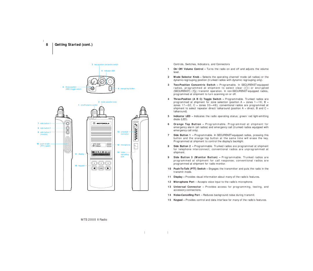
8 | Getting Started (cont.) |
|
|
3
5 indicator LED
| 11 | 13 |
| 9 | 15 |
| 7 | 1 |
| 5 | 3 |
4 | A | 6 orange top button |
(ABC) toggle switch | B | |
C |
| |
|
|
2 mode selector knob
1on/off/volume control
Controls, Switches, Indicators, and Connectors
1 | On/Off/Volume Control – Turns the radio on and off and adjusts the volume |
| level. |
2 | Mode Selector Knob – Selects the operating channel/mode (all radios) or the |
| |
3 | |
| radios, programmed at shipment to select clear ( ) or encrypted |
| (SECURENET) ( ) transmit operation. In |
| programmed at shipment to turn scanning on or off. |
4 | |
| programmed at shipment for zone selection (position A = zones |
| zones |
| shipment to select repeater direct/talkaround (position A = direct; B and C = |
| talkaround). |
5 | Indicator LED – Indicates the radio operating status; green/red |
| diode (LED). |
7side button 1
8side button 2
9side button 3 (monitor)
10
11display
| 13 | universal |
|
| connector |
MTS 2000 | 12 | microphone |
| ||
| 14 | noise- |
|
| cancelling |
|
| port |
6 | Orange Top Button – Programmable. Programmed at shipment for |
| emergency alarm (all radios) and emergency call (trunked radios equipped with |
| emergency call only). |
7 | Side Button 1 – Programmable. In |
| button and the orange top button at the same time will erase the key. |
| Programmed at shipment to control the display's backlight. |
8 | Side Button 2 – Programmable. Trunked radios are programmed at shipment |
| for telephone interconnect; conventional radios are unprogrammed at |
| shipment. |
9 | Side Button 3 (Monitor Button) – Programmable. Trunked radios are |
| programmed at shipment for call response; conventional radios are |
| programmed at shipment for radio monitor. |
15keypad
HOME
10 | |
| transmit mode. |
11 | Display – Provides visual information about many of the radio’s features. |
12 | Microphone Port – Accepts voice input to the radio’s microphone. |
13 | Universal Connector – Provides access for programming, testing, and |
| accessory connections. |
14 | |
15 | Keypad – Provides control and data interface for many of the radio’s features. |