Introduction
Installation
Troubleshooting Glossary License
5Plug the power cord into the +12VDC connector on the VoIP cable modem and the electrical outlet. For an Uninterruptible Power Supply (UPS), plug the cord into the +12VDC connector on the VoIP cable modem and the UPS and plug the UPS into the electrical outlet.
For a power adapter, plug the adapter into the POWER connector on the VoIP cable modem and the electrical outlet. For a UPS, plug the cord into the POWER connector on the VoIP cable modem and the UPS and plug the UPS into the electrical outlet. This turns on the SURFboard VoIP cable modem. You do not need to unplug it when not in use.
6Check that the lights on the VoIP cable modem front cycle through this sequence:
•
•
•
•
Power flashes during the
Receive flashes while scanning for the receive (downstream) channel and changes to solid green when it is connected.
Send flashes while scanning for the send (upstream) channel and changes to solid green when it is connected. If you use the internal
Online flashes while the VoIP cable modem downloads configuration data and changes to solid green when the download is complete.
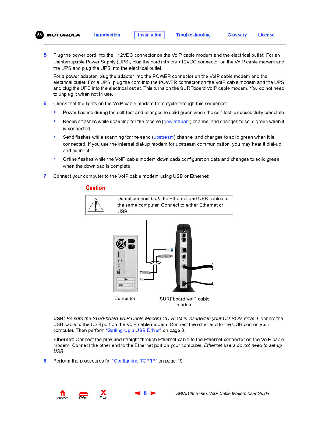
7Connect your computer to the VoIP cable modem using USB or Ethernet:
Caution
Do not connect both the Ethernet and USB cables to the same computer. Connect to either Ethernet or
USB
Computer |
TEL 1 |
TEL 2 |
ETHERNET USB CABLE![]()
![]()
![]()
![]() +12VDC
+12VDC ![]()
SURFboard VoIP cable
modem
USB: Be sure the SURFboard VoIP Cable Modem
Ethernet: Connect the provided
8Perform the procedures for “Configuring TCP/IP” on page 19.
Home Print
X | 8 | SBV5120 Series VoIP Cable Modem User Guide |
Exit |
|
|
