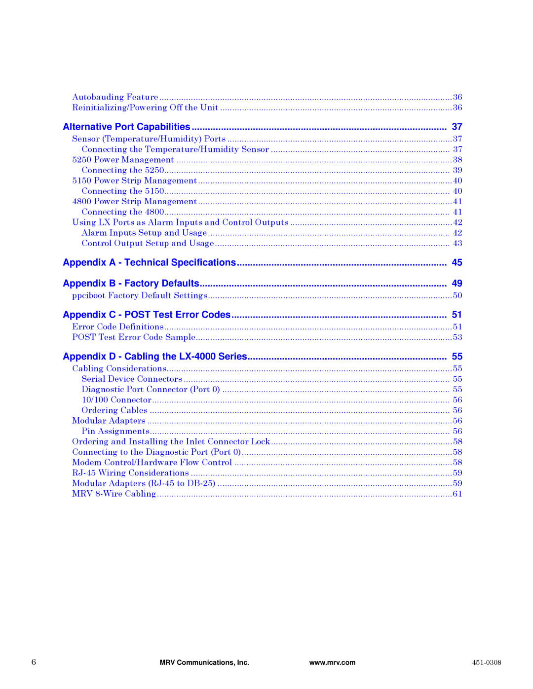
Autobauding Feature | 36 |
Reinitializing/Powering Off the Unit | 36 |
Alternative Port Capabilities | 37 |
Sensor (Temperature/Humidity) Ports | 37 |
Connecting the Temperature/Humidity Sensor | 37 |
5250 Power Management | 38 |
Connecting the 5250 | 39 |
5150 Power Strip Management | 40 |
Connecting the 5150 | 40 |
4800 Power Strip Management | 41 |
Connecting the 4800 | 41 |
Using LX Ports as Alarm Inputs and Control Outputs | 42 |
Alarm Inputs Setup and Usage | 42 |
Control Output Setup and Usage | 43 |
Appendix A - Technical Specifications | 45 |
Appendix B - Factory Defaults | 49 |
ppciboot Factory Default Settings | 50 |
Appendix C - POST Test Error Codes | 51 |
Error Code Definitions | 51 |
POST Test Error Code Sample | 53 |
Appendix D - Cabling the | 55 |
Cabling Considerations | 55 |
Serial Device Connectors | 55 |
Diagnostic Port Connector (Port 0) | 55 |
10/100 Connector | 56 |
Ordering Cables | 56 |
Modular Adapters | 56 |
Pin Assignments | 56 |
Ordering and Installing the Inlet Connector Lock | 58 |
Connecting to the Diagnostic Port (Port 0) | 58 |
Modem Control/Hardware Flow Control | 58 |
59 | |
Modular Adapters | 59 |
MRV | 61 |
6 | MRV Communications, Inc. | www.mrv.com |
|
