|
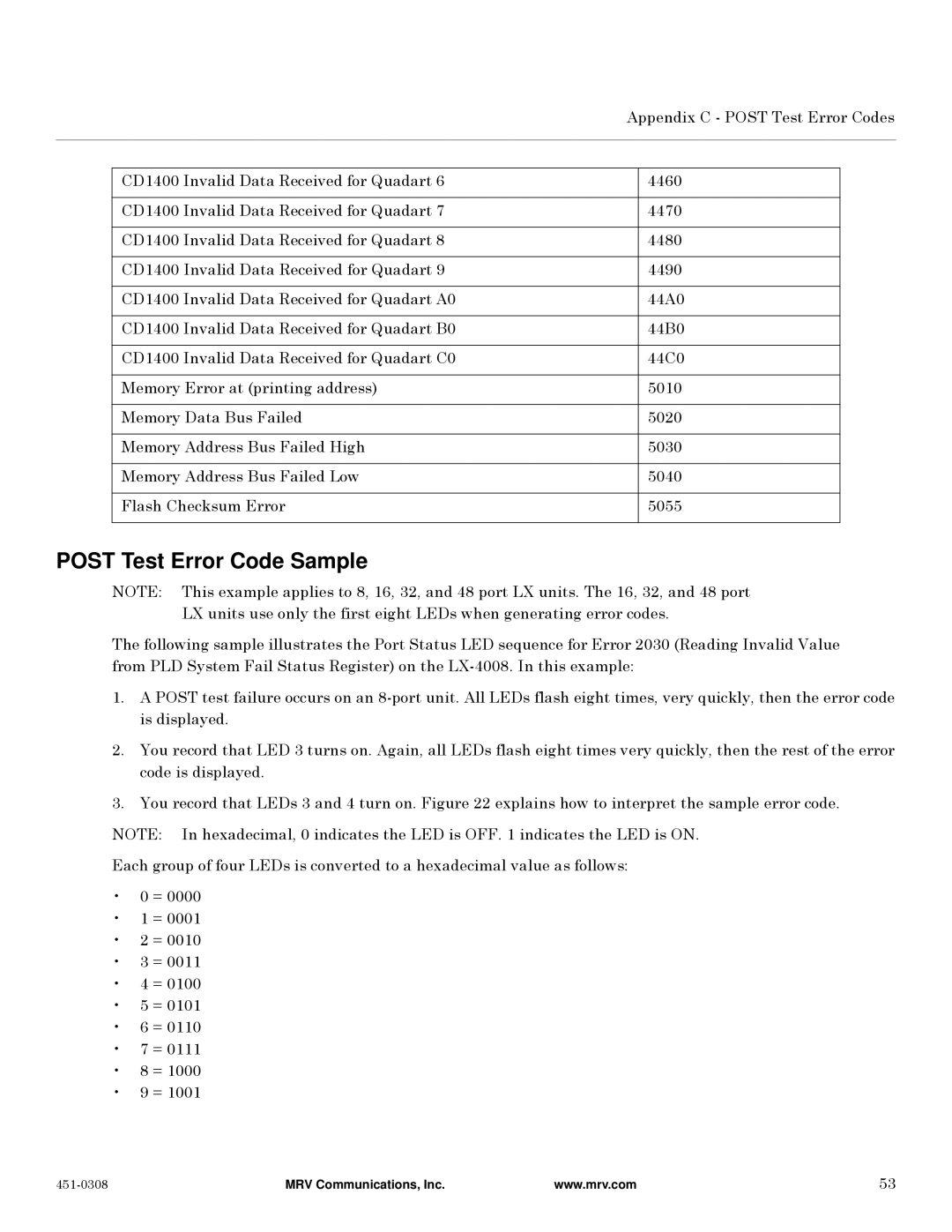
| Appendix C - POST Test Error Codes | ||
|
|
|
|
|
|
|
|
|
|
| CD1400 Invalid Data Received for Quadart 6 |
| 4460 |
|
|
|
|
|
|
| CD1400 Invalid Data Received for Quadart 7 |
| 4470 |
|
|
|
|
|
|
| CD1400 Invalid Data Received for Quadart 8 |
| 4480 |
|
|
|
|
|
|
| CD1400 Invalid Data Received for Quadart 9 |
| 4490 |
|
|
|
|
|
|
| CD1400 Invalid Data Received for Quadart A0 |
| 44A0 |
|
|
|
|
|
|
| CD1400 Invalid Data Received for Quadart B0 |
| 44B0 |
|
|
|
|
|
|
| CD1400 Invalid Data Received for Quadart C0 |
| 44C0 |
|
|
|
|
|
|
| Memory Error at (printing address) |
| 5010 |
|
|
|
|
|
|
| Memory Data Bus Failed |
| 5020 |
|
|
|
|
|
|
| Memory Address Bus Failed High |
| 5030 |
|
|
|
|
|
|
| Memory Address Bus Failed Low |
| 5040 |
|
|
|
|
|
|
| Flash Checksum Error |
| 5055 |
|
|
|
|
|
|
POST Test Error Code Sample
NOTE: This example applies to 8, 16, 32, and 48 port LX units. The 16, 32, and 48 port LX units use only the first eight LEDs when generating error codes.
The following sample illustrates the Port Status LED sequence for Error 2030 (Reading Invalid Value from PLD System Fail Status Register) on the
1.A POST test failure occurs on an
2.You record that LED 3 turns on. Again, all LEDs flash eight times very quickly, then the rest of the error code is displayed.
3.You record that LEDs 3 and 4 turn on. Figure 22 explains how to interpret the sample error code. NOTE: In hexadecimal, 0 indicates the LED is OFF. 1 indicates the LED is ON.
Each group of four LEDs is converted to a hexadecimal value as follows:
•0 = 0000
•1 = 0001
•2 = 0010
•3 = 0011
•4 = 0100
•5 = 0101
•6 = 0110
•7 = 0111
•8 = 1000
•9 = 1001
MRV Communications, Inc. | www.mrv.com | 53 |
