Appendix D - Cabling the
LX Series
Connector
Female
Supports RING
LX Series | Male | |
Connector | Connector | |
CTS | 1 | 1 |
DTR | 2 | 2 |
XMT | 3 | 3 |
GND | 4 | 4 |
GND | 5 | 5 |
RCV | 6 | 6 |
DCD | 7 | 7 |
RTS | 8 | 8 |
|
|
|
|
| Modular | Modem |
|
| ||||||
|
|
|
|
| Adaptor | Cable |
|
| ||||||
Male | Straight Through Male |
|
|
|
|
|
|
|
| |||||
Cable |
|
|
|
|
|
|
|
|
|
|
|
| ||
|
| Female |
|
|
|
|
|
|
|
| ||||
|
|
|
|
|
|
|
|
|
|
|
|
| ||
|
|
|
|
|
|
|
|
|
| |||||
|
|
|
|
|
|
|
|
|
|
|
|
| ||
|
|
|
| To Modem |
|
| ||||||||
|
|
|
|
|
| |||||||||
|
|
|
|
|
| Male |
|
| ||||||
|
|
|
|
|
|
|
|
|
|
|
|
|
| |
| Male |
| Female | Male | DCE Device | |||||||||
| Connector |
| Connector | Connector | Pin Signal | |||||||||
| 1 | 1 |
|
|
|
|
| 22 | RI | |||||
|
|
|
|
|
| |||||||||
| 2 | 2 |
|
|
|
|
| 20 | DTR | |||||
|
|
|
|
|
| |||||||||
| 3 | 3 |
|
|
|
|
| 2 |
| TXD | ||||
|
|
|
|
|
|
| ||||||||
| 4 | 4 |
|
|
|
| 7 |
| GND | |||||
|
|
|
|
|
| |||||||||
| 5 | 5 |
|
|
|
|
|
|
| 3 |
| RXD | ||
|
|
|
|
|
|
|
|
| ||||||
| 6 | 6 |
|
|
|
|
| |||||||
|
|
|
|
|
| |||||||||
| 7 | 7 |
|
|
|
| 8 |
| CD | |||||
|
|
|
|
|
| |||||||||
| 8 | 8 |
|
|
| 4 |
| RTS | ||||||
|
|
|
|
|
|
| 5 |
| CTS | |||||
Straight Through Cable | Adaptor Wiring |
| (Female |
|
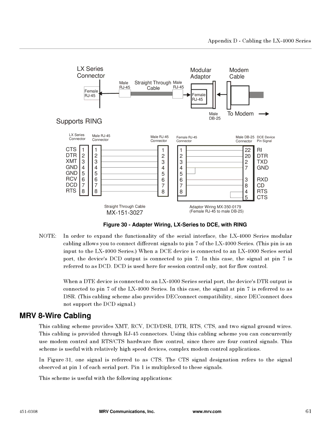
Figure 30 - Adapter Wiring, LX-Series to DCE, with RING
NOTE: In order to expand the functionality of the serial interface, the
When a DTE device is connected to an
MRV 8-Wire Cabling
This cabling scheme provides XMT, RCV, DCD/DSR, DTR, RTS, CTS, and two signal ground wires. This cabling is provided through
In Figure 31, one signal is referred to as CTS. The CTS signal designation refers to the signal observed at pin 1 of each serial port. Pin 1 is multiplexed to these signals.
This scheme is useful with the following applications:
MRV Communications, Inc. | www.mrv.com | 61 |