User Guide
User Guide
Record of Revisions
Contents
Command Mode
Callback Security and Remote Configuration
Manual Dial and Automatic Answer
Registers
Modem Testing
DIP-Switch Settings
Warranty, Service and Tech Support
Appendixes
Page
Introduction and Description
How To Use This Manual
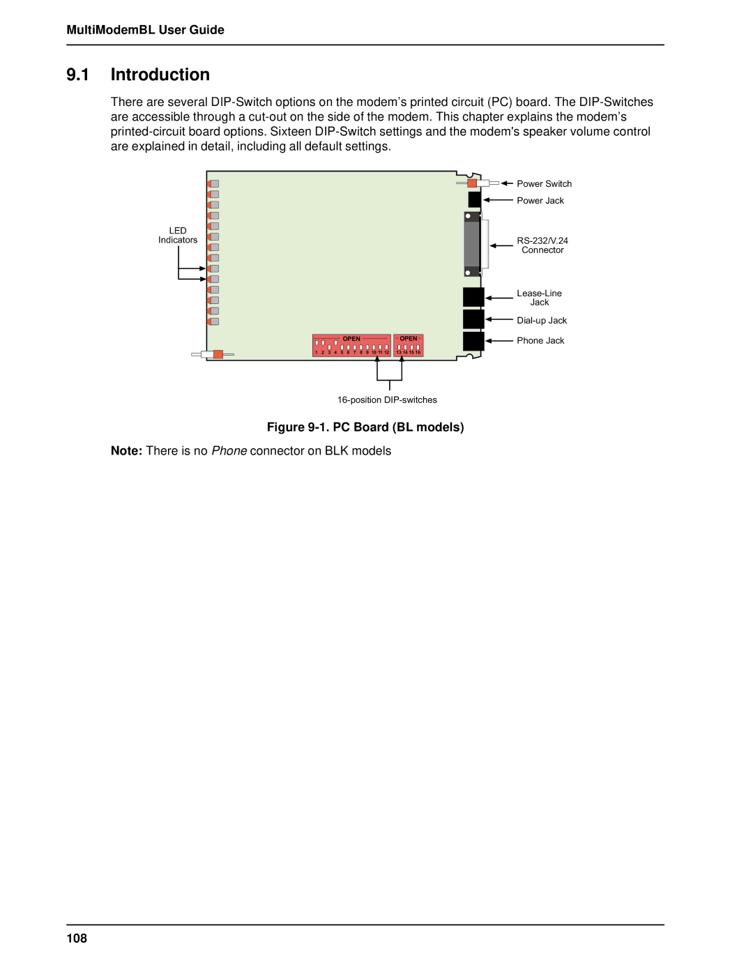
Introduction
AT Command Mode Operation
Callback and Remote Configuration
Testing Your Modem
DIP-Switches
Modem Features
1 2834 Series Features
2 1932 Series Features
3 1432 Series Features
Fax Features
Technical Specifications
Mode of Operation
Intelligent Features
Command Buffer
Introduction and Description
Fax Carrier Frequencies
Lease Line Restoral
Carrier Frequencies
Carrier Frequencies 300 bps Bell Standard
Connectors
Diagnostics
Indicators
Operating Temperature
Power
Modem LED Indicators
Models Only
Controls on PC Board
MultiModemBL User Guide
Installation and Connection
What is in Your Modem Package?
Unpacking MT2834BL shown
Installation
Safety Warnings
Installation Procedure
MultiModemBL/BLI Connections
Cabling Procedure MT1432BLK and MT2834BLK
MultiModemBLK Connections
Loading Trio DataFAX Software
Installation and Connection
Is Your Modem Ready for Use?
Software Configuration and Modem Basics
Serial Port Limitations
How Can You Identify Your Uart Type?
Configuring Your Software
Configuring Software for Your Modem
Software Configuration
16550 Uart and Windows
Changing Default Parameters
PC Initialization Strings
Other Parameters
Configuring Software for Your Computer
Configuring Software for the Remote System
Macintosh Initialization
Terminal Emulation
When to Disable Data Compression
Disabling Error Correction
File Transfer Protocols
AT &F S0=0 X4 &E14 M
Answer/Originate Voice/Data Toggle Switch
Modem Basics
Simple Operations
MultiModemBL User Guide
Manual Dial and Automatic Answer
Dialing/On-Line/Answering
Manual Dial Backup Call Termination
Dial Backup and Leased Line Restoral
Automatic Leased Line Restoral Operation
Manual Dial and Automatic Answer
Dial-Up Operation
Manual Call Origination
Automatic Answering
Manual Answering
Abort Timer
Handshaking Details
Call Termination
Command Mode
AT Command Editing
Command Mode
Functional Modes
Summary of AT Commands
Normal Mode
Auto-Reliable Mode
Reliable Mode
Flow Control Disabled
Enable/Disable Reading Line Probe From DSP during handshake
Display of Signal Strength Information
Passwords for Callback Phone Numbers
Callback Security Enable/Disable
Result Codes
Multi-Tech Result Codes Series
MultiModemBL User Guide Standard AT Result Codes Series
Dialing Commands Dialing Action Commands
Dial Command D
Continuous Redial not used in BLI/BLK a or
Dialing a Stored Number N
Dial Modifier Commands
Voice/Data Dialing $VD
Pulse or Tone Dial P T
Set Pulse Dial Ratios &P Not used in BLK
Return to Command Mode After Dial Command Execution
Reverse the Mode of Operation R
Automatic Pauses in Dialing
Long Space Disconnect Y
Calling Card Detect Tones $
Quiet Answer @
Phone Number Memory Commands
Storing Phone Numbers D...N
Number Linking NN
Listing Numbers Stored in Memory L
Configuration and Default Storage Commands
Loading Factory Defaults &F
Modem Reset Z
Async/Sync Mode Switching &M
Unix Uucp Spoofing $SP
Synchronous Transmit Clock Select &X
Command Response Result Code Commands
Echo Command Mode Characters E
Result Codes Enable/Disable and No Response Answer Q
Result Codes Multi-Tech or Standard AT &Q
Result Codes Basic and Extended and Call Progress Selection
Phone Line Conditioning Commands
Enable/Disable Trelis Coded Modulation #T
Guard Tones Not Used in BLI or BLK Models &G
Bell/V.21 Tone Not Used in BLK Models B
Fallback Modes When On-Line #F
Enable/Disable Lowspeed Fast Connect $FC 2834 Series only
Cleardown at Disconnect &CD 2834 Series only
Auto Speed Detect #A
7 RS-232C Interface Control Commands
Carrier Detect Control &C
Data Terminal Ready Control &D
CTS Control &R
Data Set Ready Control &S
CTS/RTS Interaction Control &RF
DSR/CD Interaction Control &SF
Error Correction Commands
Normal Mode &E0
Auto-Reliable Mode &E1
Reliable Mode &E2
Mode Select #L
Originate Mode
Answer Mode
Auto-Reliable Buffering $A
Enable/Disable Auto Reliable Fallback Character $F
Error Correction/300bps $E
Retransmit Count $R
Flow Control Commands
Hardware Flow Control &E4
Xon/Xoff Flow Control &E5
Modem-Initiated Flow Control
Xon/Xoff Pass-Through &E7
Send Xon/Xoff Characters #X
Hewlett-Packard ENQ/ACK Pacing &E9
Normal Mode Modem Flow Control On &E11
Terminal/Computer Initiated Pacing &E13
Maximum Block Size &BS
Parity Selection #P
Normal/Auto-Reliable/Reliable Mode Commands
Xon/Xoff Pass-Through Commands
Enq/Ack Pacing Commands
Speed Conversion Commands
Speed Conversion $BA
Modem Baud Rate $MB
Command Mode Series
Serial Port Baud Rate $SB
Immediate Action Commands
Listing On-Line Diagnostics L8
Off Hook H
Line Probe Commands 2834 Series only
Force Answer Mode a
Exiting Command Mode, Going Back On-Line O
MultiModemBL User Guide
Registers
Number of Rings Until Modem Answers
Rings Which Have Occurred
Escape Code Character
Return Character
Time for Carrier Abort Timer
Line Feed Character
Backspace Character
Wait Time for Dial Tone
S10 Carrier Loss Disconnect Delay Time
S13 Remote Configuration Escape Character
Carrier Detect Response Time
S11 Tone Dialing Tone Spacing and Duration
S15 Callback Time Delay
S19 Dial-Back Timer
S16 Callback Attempts
S17 Changing Break Time
S26 Failed Password Attempts
S29 Local Inactivity Timer
S24 PBX/CBX Disconnect Drop Time for DSR/CTS/CD
S25 DTR Dropout Time
S30 Inactivity Timer
S32 Time Elapse for Escape Sequence
S36 Time Between DTR Inactive and Modem Off-Hook
S37 Time Between DTR Active and Modem On-Hook
S48 Program V.34bis Connect Speeds 2834 Series only
Reading and Assigning S-Register Values
Examples of Assigning Values
Examples of Reading Values
AT Command and S-Register Summary
Callback Security and Remote Configuration
Callback Feature Description
Remote Configuration Description
Callback Security and Remote Configuration
To change your Remote Configuration feature status
To set parity of the password/message prompt
AT#CBN0xxxxxxxxxxCR
AT#CBN1xxxxxxxxxxCR
Callback Operational Sequence Procedures
Remote Configuration Procedures
Remote Configuration Operation Procedures StepProcedure
Remote Configuration and Callback Security AT Commands
Assign Passwords for Callback Phone Numbers #CBN
Callback Security Enable/Disable
Change Login Password
Erase Callback Password
Erase Callback Phone Number #RDNxx
Remote Configuration/Callback Security S-Registers
MultiModemBL User Guide
Modem Testing
Introduction
Modem Testing
Local Analog Loopback Test/V.54 Loop
Digital Loopback Test/V.54 Loop 2 Local/Manual
100
Digital Loopback Test/V.54 Loop 2 Remote/Automatic
101
Back-to-Back Test
4A. Back-to-Back Test Cabling
Synchronous Mode Testing
Local Analog Loopback Test Synchronous Mode
Digital Loopback Test Local/Manual Synchronous Mode
Synchronous Mode Digital Loopback Test local/manual 104
Digital Loopback Test Remote/Automatic Synchronous Mode
Synchronous Mode Digital Loopback Test remote/automatic 105
MultiModemBL User Guide 106
DIP-Switch Settings
PC Board BL models 108
DIP-Switch Option Settings
DIP-Switch Settings
109
Switch #4 AS/400 Mode Synchronous Mode/Leased Line/Dial-UP
1432 Series
110
111
112
113
Speaker Volume Control
MultiModemBL User Guide Series
114
Recording Option Configurations
Switch Function Position Effect
115
DIP Switches #13-14
DIP Switches #15-16
116
Warranty, Service and Tech Support
Limited Warranty
On-line Warranty Registration
118
Service
Warranty, Service and Tech Support
Tech Support
Recording Modem Information
Multi-Tech BBS
To log on to the Multi-Tech BBS
To Download a file
Using FlashPro to Upgrade Modem Firmware
About the Multi-Tech Fax-Back Service
Upgrading the MultiModem
About Multi-Tech’s Internet Presence
About Ordering Accessories
SupplyNet Online Ordering Instructions
122
Appendixes
Appendix a Troubleshooting
None of the LEDs Light When the Modem Is On
Modem Does Not Respond to Commands
124
Appendix a Troubleshooting
125
Modem Dials But Cannot Make a Connection
126
Modem Cannot Connect When Answering
Modem Disconnects While On-line
File Transfer Is Slower Than It Should Be
127
Am Losing Data
Am Getting Garbage Characters on the Monitor
128
Appendix B Ascii Conversion Chart
129
Appendix C Dial Pulse and Tone-Dial Frequencies
Dial Pulses
Tone Dial Frequencies
130
Appendix D AT Command Summary
Command Values Description
$An
#An
BS n
$BA n
CD n
SN d
$EBn
#Fn
$FCn
$Fn
$Hn
L10
#Ln
$MBn
NdNe
$Rn
RFn
Sr=n
$SBn
SFn
$SPn
#Tn
#Xn
+++ATCR
137
Callback Security/Remote Configuration Command Summary
Password Command Summary
25bis Commands
Appendix E DIP-Switch Summary
Asynchronous Mode
140
Synchronous Mode
Appendix E DIP-Switch Summary
141
142
Appendix F S-Register Summary
S24
S25
S26
S29
Appendix G Result Code Summary
Appendix G Result Code Summary
Terse Digit Verbose Words Effect
145
146
Delayed and Forbidden Numbers
Appendix H V.25bis Operation
25bis Operation
Appendix H V.25bis Operation
25bis DIP-Switches
25bis Set-Up and Initialization
148
25bis Mode AT Commands
25bis Responses Result Codes
149
25bis AT Commands
Enable/Disable V.25bis Mode $V Command
Change Serial Baud Rate CSP Command
Dial Phone Number Provided CRN Command
Listing Delayed Phone Numbers RLD Command
Listing Forbidden Phone Number RLF Command
Disregard or Connect to Incoming Calls DIC or CIC Command
DTR Dialing $D Command
ITU V.25bis Country Specific Information
Italy
Switzerland
Austria
Appendix H V.25bis Operation France
Belgium
Singapore
153
Appendix I MultiModemBL Cables
Figure I-1. RS232 Cable IBM PC
Appendix J RS-232C Interface Specifications
Figure I-4. MAC Cable 155
Appendix J RS-232C Interface Specifications
Signal Function Assignment Circuit Source
Pin Designation Eia
156
Signal Ground Pin 7, SG AB
Received Data Pin 3, RD BB
Request To Send Pin 4, RTS CA
Clear To Send Pin 5, CTS CB
Ring Indicator Pin 22, RI CE
Test Voltage Pin 9
Transmit Clock Pin 15, TC DB
Receive Clock Pin 17, RC DD
Terminal Busy Out of Service Pin 25, OOS
External Transmit Clock Pin 24, XTC
159
160
EMC, Safety and Terminal Directive Compliance
Compliance with European Community Requirements
European Directives User Guide Statement
Appendix K Regulatory Information
International Modem Restrictions
New Zealand Telecom Warning Notice
162
FCC Regulations for Telephone Line Interconnection
163
Canadian Limitations Notice
Class a Statement
FCC Part
Industry Canada
Index
165
Functional Description of RS232C SIG
166
167
168
XON/XOFF