MultiFRAD
Back Panel Description
VOICE/ |
|
| VOICE/ |
|
| VOICE/ |
|
|
|
| VOICE/ |
|
| |
FAX |
|
| FAX |
|
| FAX |
|
|
|
| FAX |
|
| |
CHANNEL |
|
| CHANNEL |
|
| CHANNEL |
|
|
|
| CHANNEL |
|
| |
8 |
|
| 7 |
|
| 6 |
|
|
|
|
| 5 |
|
|
E&M | FXO | FXS |
| E&M | FXO | FXS |
| E&M | FXO | FXS |
| E&M | FXO | FXS |
VOICE/ |
|
| VOICE/ |
|
| VOICE/ |
|
|
|
| VOICE/ |
|
| |
FAX |
|
| FAX |
|
| FAX |
|
|
|
| FAX |
|
| |
CHANNEL |
|
| CHANNEL |
|
| CHANNEL |
|
|
|
| CHANNEL |
|
| |
4 |
|
| 3 |
|
| 2 |
|
|
|
|
| 1 |
|
|
CHANNEL | 10 |
| CHANNEL | 8 |
| CHANNEL | 6 |
|
| CHANNEL | 4 |
| CHANNEL | 2 (RS232/V.35) |
CHANNEL | 9 |
| CHANNEL | 7 |
| CHANNEL | 5 |
|
| CHANNEL | 3 |
| CHANNEL | 1 (RS232/V.35) |
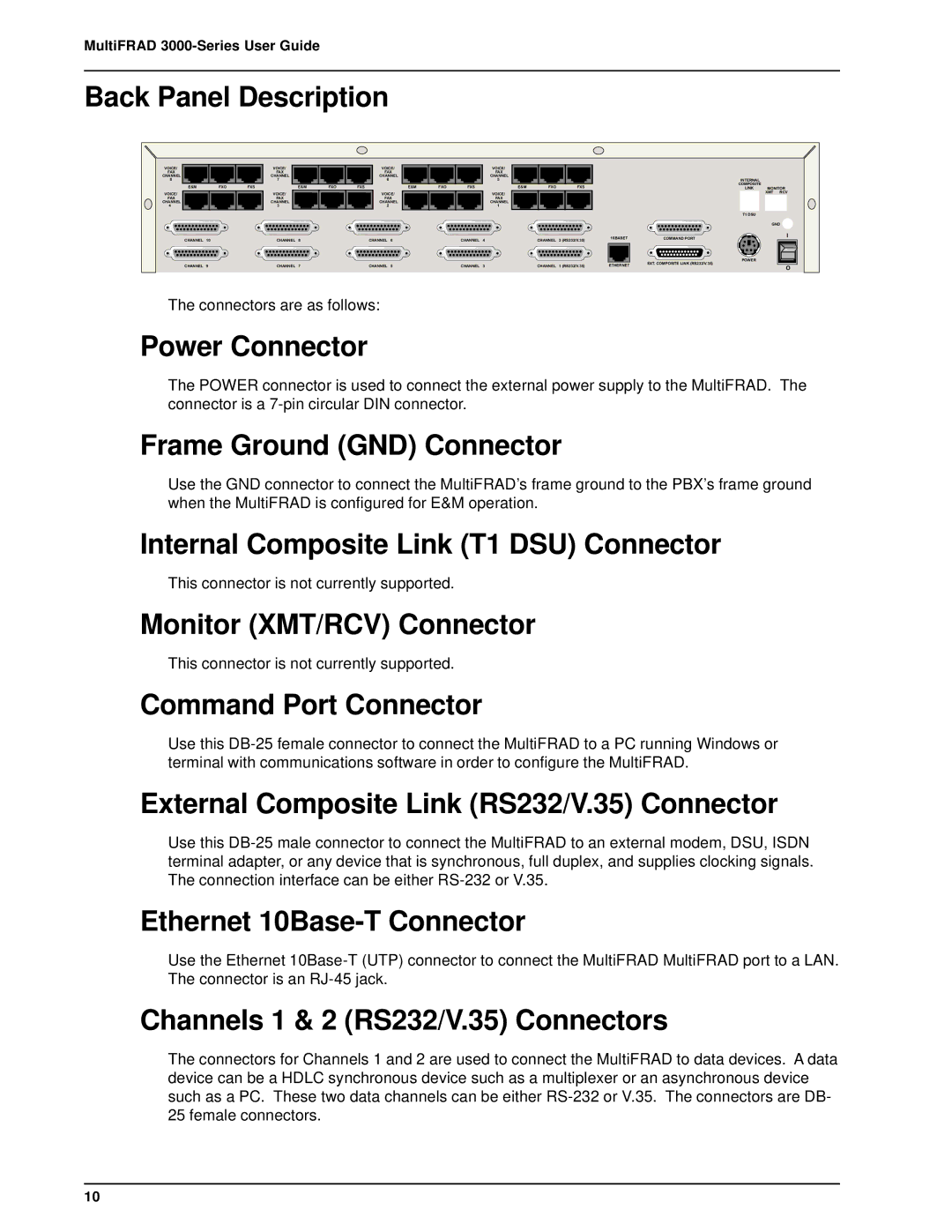
The connectors are as follows:
| INTERNAL |
|
|
| COMPOSITE |
|
|
| LINK | MONITOR | |
|
| XMT | RCV |
| T1 DSU |
|
|
|
| GND | |
10BASET | COMMAND PORT |
| I |
|
| ||
| POWER |
|
|
ETHERNET | EXT. COMPOSITE LINK (RS232/V.35) |
| O |
|
|
| |
Power Connector
The POWER connector is used to connect the external power supply to the MultiFRAD. The connector is a
Frame Ground (GND) Connector
Use the GND connector to connect the MultiFRAD’s frame ground to the PBX’s frame ground when the MultiFRAD is configured for E&M operation.
Internal Composite Link (T1 DSU) Connector
This connector is not currently supported.
Monitor (XMT/RCV) Connector
This connector is not currently supported.
Command Port Connector
Use this
External Composite Link (RS232/V.35) Connector
Use this
Ethernet 10Base-T Connector
Use the Ethernet
Channels 1 & 2 (RS232/V.35) Connectors
The connectors for Channels 1 and 2 are used to connect the MultiFRAD to data devices. A data device can be a HDLC synchronous device such as a multiplexer or an asynchronous device such as a PC. These two data channels can be either
10