MQ Power DCA-100SSJU Whisperwatttm Generator
Table of Contents
Heres HOW to GET Help
Table of Contents
USA
Parts Ordering Procedures
Rules for Safe Operation
General Safety
Radiator
Rules for Safe Operation
Loading and Unloading Crane
Battery
Rules for Safe Operation
Maintenance Safety
Transporting
Emergencies
DCA-100SSJU Towing Rules for Safe Operation
Towing Safety Precautions
Explanation of Chart
DCA-100SSJU -TRAILER-SAFETY Guidelines
Coupler Type of hitch used on the trailer for towing
TRLR-10XF
DCA-100SSJU -TRAILER-SPECIFICATIONS
Electrical
DCA-100SSJU -TRAILER-SPECIFICATIONS
DCA-100SSJU Trailer Braking System
Electric Brake Adjustment
Brakes
Electric Brakes
Hydraulic/Air/Surge Brakes
DCA-100SSJU -TRAILER Braking System
Tires/Wheels/Lug Nuts
DCA-100SSJU Trailer Tires & Suspension
Tire Wear/Inflation
Suspension
Lug Nut Torque Requirements
Torque Ft.-Lbs
Never use an pneumatic air gun to tighten wheel lug nuts
DCA-100SSJU -TRAILERWIRING Diagrams
Electric Brake Troubleshooting
DCA-100SSJU -TRAILER-BRAKE Troubleshooting
Hydraulic Brake Troubleshooting
DCA-100SSJU -TRAILER-BRAKE Troubleshooting
DCA-100SSJU Generator Decals
DCA-100SSJU Generator Decals
Generator Specifications
DCA-100SSJU Specifications
DCA-100SSJU General Information
Major Components
DCA-100SSJU Major Components
Dimensions
DCA-100SSJU Dimensions TOP, Side and Front
Page
Control Panel
DCA-100SSJU Control Panel
DCA-100SSJU Control Panel
Engine Operating Panel
DCA-100SSJU Engine Operating Panel with KEY
Fuel Gauge Indicates amount of diesel fuel available
DCA-100SSJU Engine Operating Panel with KEY
DCA-100SSJU Engine Operating Panel with Mpec
DCA-100SSJU Engine Operating Panel with Mpec
DCA-100SSJU Output Terminal Panel Overview
Connecting Load
Circuit Breakers
Volt Receptacle
DCA-100SSJU Output Terminal Panel Overview
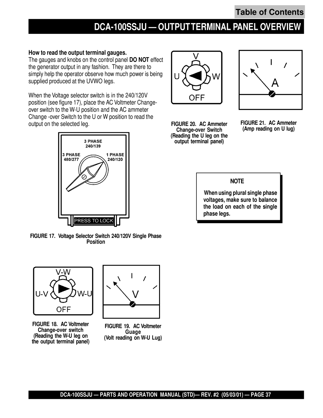
DCA-100SSJU Outputterminal Panel Overview
AC Ammeter
How to read the output terminal gauges
480/240V Hard Wire Hookup
240/120V Hard Wire Hookup
Phase, 480V, 440V, or 416 Volt
Single Phase 480V, 440V, or 416 Volt
Single Phase 277V, 254V, or
Phase, 240V, 220V, or 208 Volt
Single Phase 240V, 220V, or 208 Volt
Single Phase 139V, 127V, or
Single Phase 120 Volt
Voltage Selector Switch- Single Phase 240/120V Position
Single Phase, 240 Volt
Outdoor Installation
DCA-100SSJU Installation
Indoor Installation
Typical Generator Grounding Application
DCA-100SSJU Installation
DCA-100SSJU PRE-SETUP
Lubrication Oil
DCA-100SSJU PRE-SETUP
Manual
Coolant
Air Cleaner Fan Belt Tension
Cleaning the Radiator
Operation in Freezing Weather
When connecting battery do the following
Battery Cable Installation
Wiring
Piping and Hose Connection
Three Phase Load
Single Phase Load
DCA-100SSJU Load Application
Watts =1.732 x Voltage x Amperage
Before Starting Generator and Control Panel
Before Starting Engine
Close all engine enclosure doors Figure
DCA-100SSJU Generator START-UP Procedure Manual
Frequency Meter Hz
Place the Off/Manual/Auto switch in the Auto position up
DCA-100SSJU Generator START-UP Procedure Auto
DCA-100SSJU Generator Shutdown Procedure
DCA-100SSJU Maintenance
Inspection / Maintenance
DCA-100SSJU Maintenance
Engine Troubleshooting
DCA-100SSJU -TROUBLESHOOTING Engine
DCA-100SSJU -TROUBLESHOOTING Engine
Engine & Generator Troubleshooting
DCA-100SSJU -TROUBLESHOOTING GENERATOR/ENGINE
Mpec Troubleshooting
DCA-100SSJU Troubleshooting Mpec
Items Found In the Items Number Column
Explanation of Code in Remarks Column
N7400296~
Qty Description
DCA-100SSJU --- Generator Assy
Generator Assy
Generator
DCA-100SSJU --- Control BOX Assy
DCA-100SSJU Control BOX Assy
DCA-100SSJU --- Control BOX Assy
DCA-100SSJU
DCA-100SSJU Engine and Radiator Assy
DCA-100SSJU Engine and Radiator Assy
DCA-100SSJU Engine and Radiator Assy
QTY Remarks
700001 to 7400296~
DCA-100SSJU --- Engine Operating Panel Assy
Engine Operating Panel Assy
DCA-100SSJU --- Output Terminal Assy
DCA-100SSJU Output Terminal Assy
Output Terminal
DCA-100SSJU --- Battery Assy
4D-2
0602220196
0602220921
0040006000
DCA-100SSJU --- Muffler Assy
DCA-100SSJU Muffler Assy
DCA-100SSJU --- Fuel Tank Assy
020108060
0605505070
0273080000
N74000027~ 031108160
Enclosure Assy
DCA-100SSJU --- Enclosure Assy
Enclosure Assy
DCA-100SSJU --- Enclosure Assy
N7400027 to
Replaces M3453200102
011208060
0601850097
DCA-100SSJU --- Rubber Seal Assy
DCA-100SSJU --- Rubber Seal Assy
DCA-100SSJU --- Decals
Decals
Effective July 1
Page
Heres HOW to GET Help