Manuals
/
Napoleon Fireplaces
/
Household Appliance
/
Indoor Fireplace
Napoleon Fireplaces
GD19N Mobile Home Installation, Gas Installation, Electrical Installation
Models:
GD19N
GD19P
1
21
36
36
Download
36 pages
28.06 Kb
18
19
20
21
22
23
24
25
Troubleshooting
Flame Characteristics
Install
Venting Application Flow Chart
Maintenance
Symptom
Accessories
Flame Adjustment
Night Light Replacement
Safety
Page 21
Image 21
Page 20
Page 22
Page 21
Image 21
Page 20
Page 22
Contents
SAFETY INFORMATION
INSTALLATION AND OPERATION INSTRUCTIONS
GD19N
GD19P
RETAIN THIS MANUAL FOR FUTURE REFERENCE
TABLE of CONTENTS
CONDITIONS AND LIMITATIONS
GENERAL INSTRUCTIONS
GENERAL INFORMATION
CARE OF GLASS AND PLATED PARTS
VENTING
HORIZONTAL VENT SECTIONS
VENT INSTALLATIONS
VERTICAL VENT SECTIONS
FOR SPECIFIC VENTING PARAMETERS, REFER TO PAGES
SPECIAL VENT INSTALLATIONS
TYPICAL VENT INSTALLATIONS
REAR EXIT
TOP EXIT
W415-0612 /C
MINIMUM AIR TERMINAL LOCATION CLEARANCES
FIREPLACE VENT EXIT
VENTING APPLICATION FLOW CHART
REAR EXIT
TOP EXIT
DEFINITIONS
TOP EXIT / HORIZONTAL TERMINATION
ELBOW VENT LENGTH VALUES
HT VT
TOP EXIT / HORIZONTAL TERMINATION
REAR EXIT / HORIZONTAL TERMINATION
H2
HT VT
REAR EXIT / HORIZONTAL TERMINATION
HT VT
TOP OR REAR EXIT VERTICAL TERMINATION
HT VT
TOP EXIT CONVERSION
HORIZONTAL INSTALLATION
INSTALLATION WALL AND CEILING PROTECTION
VERTICAL INSTALLATION
3/4”
USING FLEXIBLE VENT COMPONENTS
HORIZONTAL AIR TERMINAL INSTALLATION
VERTICAL AIR TERMINAL INSTALLATION
FIREPLACE VENT CONNECTION
AIR TERMINAL INSTALLATION
VERTICAL VENTING INSTALLATION
RESTRICTING VERTICAL VENTS
EXTENDED HORIZONTAL AND CORNER
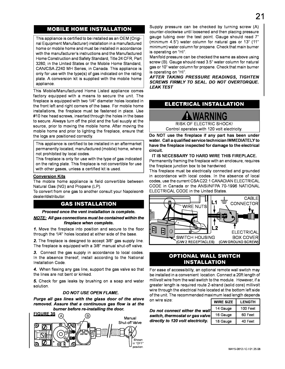
GAS INSTALLATION
MOBILE HOME INSTALLATION
ELECTRICAL INSTALLATION
OPTIONAL WALL SWITCH INSTALLATION
REAR VENT
FRAMING
TOP VENT
Combustible Framing 0 to stand-offs
FIGURES 41a&b
MINIMUM MANTEL AND ENCLOSURE CLEARANCES
FIREBOX
FRONT FACING AND INSET KIT INSTALLATION
NIGHT LIGHT REPLACEMENT
BLOWER INSTALLATION
BULB REPLACEMENT
LENS ASSEMBLY INSTALLATION
GLASS DOOR INSTALLATION AND REMOVAL
FINISHING
DOOR GLASS REPLACEMENT
LOG PLACEMENT
MAIN BURNER SWITCH
LOGO PLACEMENT
FLAME ADJUSTMENT
NIGHT LIGHTTM SWITCH
See detail for optional wall switch GD-660wiring
WIRING DIAGRAM
MAINTENANCE
OPERATION / MAINTENANCE
FOR YOUR SAFETY READ BEFORE OPERATING
OPERATING INSTRUCTIONS
PILOT INJECTOR AND ORIFICE REPLACEMENT
ADJUSTMENTS
VENTURI ADJUSTMENT
FLAME ADJUSTMENT
REPLACEMENT PARTS
REPLACEMENTS
ACCESSORIES
FOR WARRANTY REPLACEMENT PARTS, A PHOTOCOPY OF
W415-0612 /C
SYMPTOM
TROUBLE SHOOTING GUIDE
PROBLEM
TEST SOLUTION
PROBLEM
SYMPTOM
TEST SOLUTION
Pilot lights
serviced annually depending on usage
Fireplace Service History
This fireplace must be
W415-0612 /C
W415-0612 /C
Top
Page
Image
Contents