28
WIRING DIAGRAM
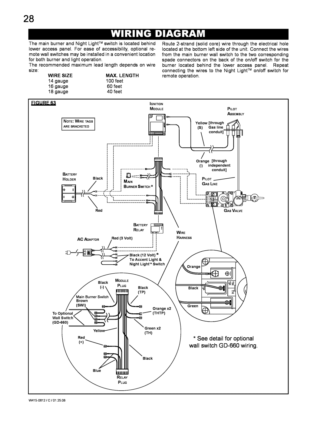
The main burner and Night LightTM switch is located behind lower access panel. For ease of accessibility, optional re- mote wall switches may be installed in a convenient location for both burner and light operation.
The recommended maximum lead length depends on wire size:
WIRE SIZE | MAX. LENGTH |
14 gauge | 100 feet |
16 gauge | 60 feet |
18 gauge | 40 feet |
Route
FIGURE 63 | IGNITION |
| MODULE |
| NOTE: WIRE TAGS |
| ARE BRACKETED |
BATTERY | Black |
|
HOLDER | MAIN | |
|
|
BURNER SWITCH *
Red
BATTERY
RELAY
AC ADAPTOR | Red (3 Volt) |
Black (12 Volt) *
To Accent Light &
Night LightTM Switch
Black | MODULE |
| |
PLUG |
| ||
Black | |||
| |||
Main Burner Switch |
| (TP) | |
|
| ||
Brown |
|
| |
(SWI) |
| Orange x2 | |
|
| ||
To Optional |
| (THTP) | |
Wall Switch |
|
| |
|
| ||
Yellow |
| Green x2 | |
| (TH) | ||
Red |
| ||
|
| ||
(+) |
|
| |
|
| Black | |
Blue |
|
| |
| RELAY |
| |
| PLUG |
|
PILOT
ASSEMBLY
Yellow [through
(S)Gas line conduit]
Orange [through
(I)independent
conduit]
PILOT
GAS LINE
GAS VALVE
WIRE
HARNESS
Orange ![]()
Black ![]()
![]()
![]()
![]()
Green