4.REQUIRED EQUIPMENT
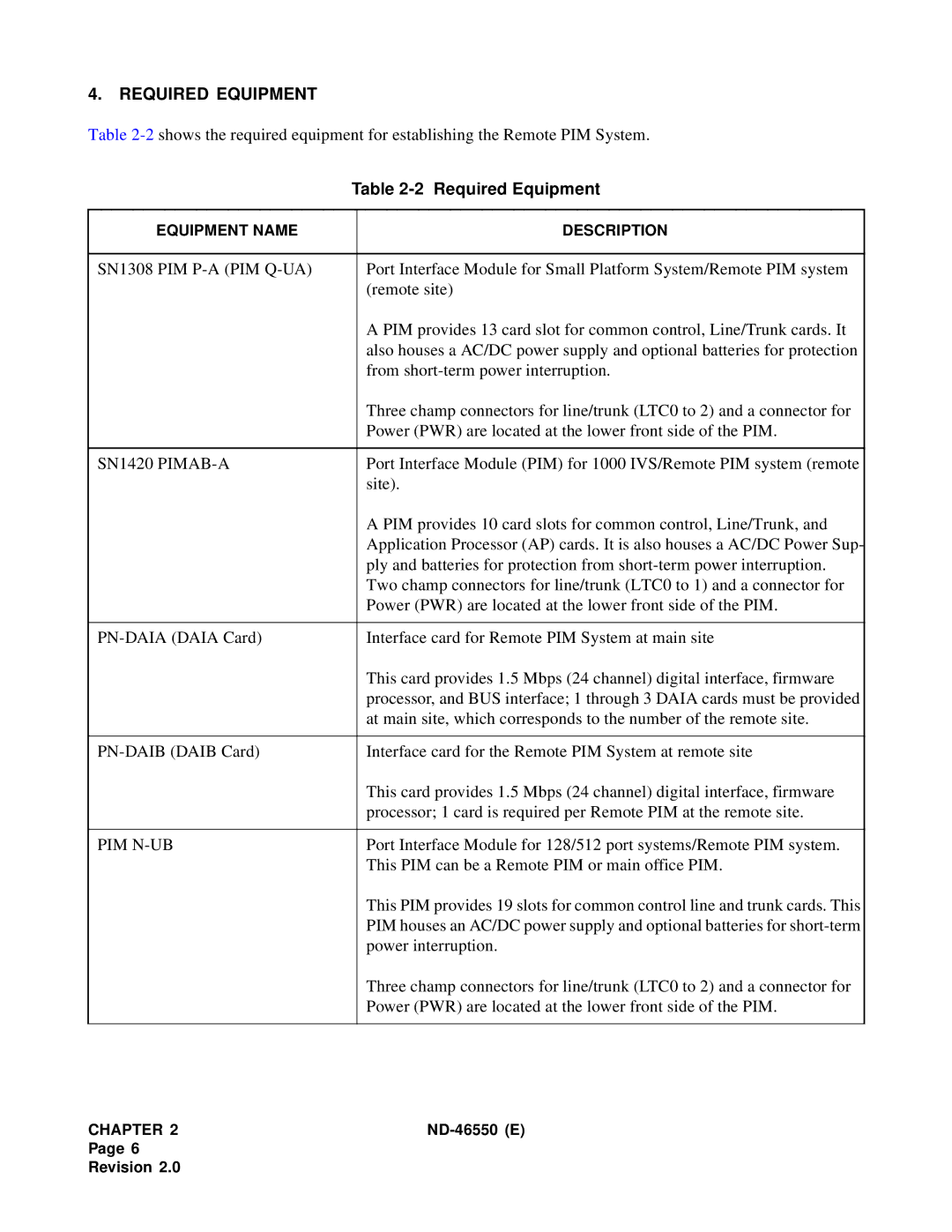
Table
| Table | |
|
|
|
EQUIPMENT NAME |
| DESCRIPTION |
|
|
|
SN1308 PIM |
| Port Interface Module for Small Platform System/Remote PIM system |
|
| (remote site) |
|
| A PIM provides 13 card slot for common control, Line/Trunk cards. It |
|
| also houses a AC/DC power supply and optional batteries for protection |
|
| from |
|
| Three champ connectors for line/trunk (LTC0 to 2) and a connector for |
|
| Power (PWR) are located at the lower front side of the PIM. |
|
|
|
SN1420 |
| Port Interface Module (PIM) for 1000 IVS/Remote PIM system (remote |
|
| site). |
|
| A PIM provides 10 card slots for common control, Line/Trunk, and |
|
| Application Processor (AP) cards. It is also houses a AC/DC Power Sup- |
|
| ply and batteries for protection from |
|
| Two champ connectors for line/trunk (LTC0 to 1) and a connector for |
|
| Power (PWR) are located at the lower front side of the PIM. |
|
|
|
| Interface card for Remote PIM System at main site | |
|
| This card provides 1.5 Mbps (24 channel) digital interface, firmware |
|
| processor, and BUS interface; 1 through 3 DAIA cards must be provided |
|
| at main site, which corresponds to the number of the remote site. |
|
|
|
| Interface card for the Remote PIM System at remote site | |
|
| This card provides 1.5 Mbps (24 channel) digital interface, firmware |
|
| processor; 1 card is required per Remote PIM at the remote site. |
|
|
|
PIM |
| Port Interface Module for 128/512 port systems/Remote PIM system. |
|
| This PIM can be a Remote PIM or main office PIM. |
|
| This PIM provides 19 slots for common control line and trunk cards. This |
|
| PIM houses an AC/DC power supply and optional batteries for |
|
| power interruption. |
|
| Three champ connectors for line/trunk (LTC0 to 2) and a connector for |
|
| Power (PWR) are located at the lower front side of the PIM. |
|
|
|
CHAPTER 2 |
Page 6
Revision 2.0
