CHAPTER 2 SYSTEM DESCRIPTION
1.SYSTEM OUTLINE
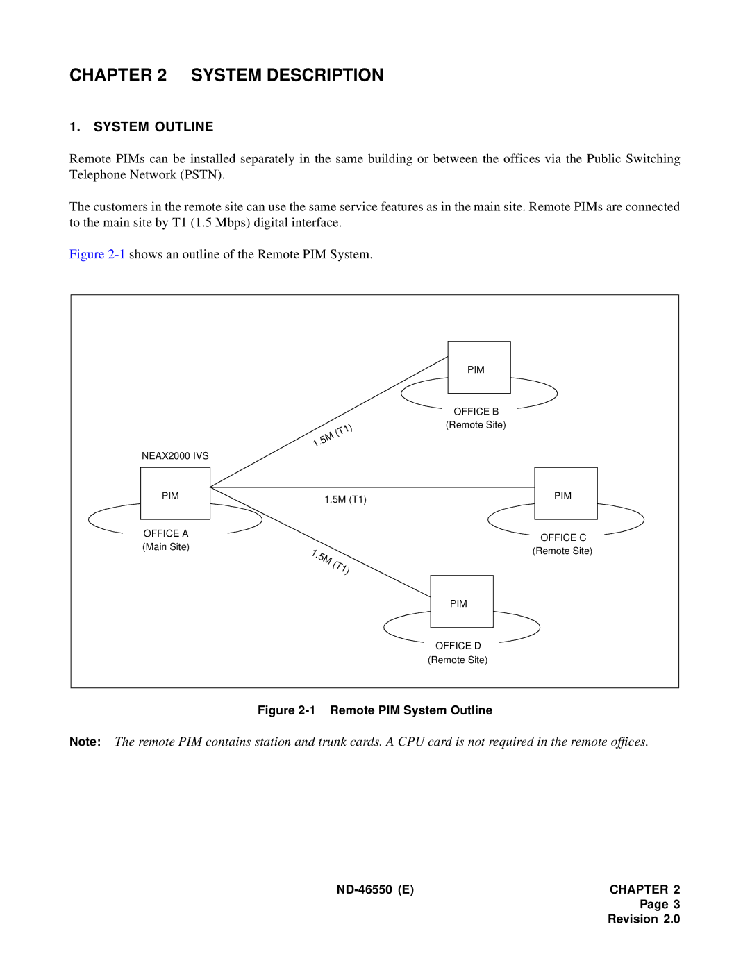
Remote PIMs can be installed separately in the same building or between the offices via the Public Switching Telephone Network (PSTN).
The customers in the remote site can use the same service features as in the main site. Remote PIMs are connected to the main site by T1 (1.5 Mbps) digital interface.
Figure 2-1 shows an outline of the Remote PIM System.
|
|
|
| PIM |
|
|
|
| OFFICE B |
|
|
| ) | (Remote Site) |
|
| 1 |
| |
|
| (T |
|
|
|
| M |
|
|
| .5 |
|
| |
| 1 |
|
|
|
NEAX2000 IVS |
|
|
|
|
PIM |
| 1.5M (T1) | PIM | |
|
|
| ||
OFFICE A |
|
|
| OFFICE C |
(Main Site) |
|
|
| |
1. |
|
| (Remote Site) | |
|
|
| ||
| 5 |
|
| |
|
| M ( |
|
|
|
| T |
|
|
|
| 1) |
| |
|
|
|
| PIM |
|
|
|
| OFFICE D |
|
|
|
| (Remote Site) |
Figure 2-1 Remote PIM System Outline
Note: The remote PIM contains station and trunk cards. A CPU card is not required in the remote offices.
| CHAPTER 2 |
Page 3
Revision 2.0
