Manuals
/
NEC
/
Computer Equipment
/
Projector
NEC
GT6000 Installation x Lens Shift Adjustable Range, Desktop/Front, Vertical, Ceiling/Front
Models:
GT6000
1
21
117
117
Download
117 pages
46.44 Kb
18
19
20
21
22
23
24
25
Troubleshooting
Specification
Install
Signal Level
Password
Timer
Power Indicator
Connecting an External Monitor
Warranty
Maintenance
Page 21
Image 21
Page 20
Page 22
Page 21
Image 21
Page 20
Page 22
Contents
LCD Projector User’s Manual
GT6000/GT5000
Important Safeguards
Important Information
Precautions
Installation
Cleaning
Power Supply
Lamp Replacement
Fire and Shock Precautions
Table of Contents
v Remote Control Features
Introduction
z Whats in the Box?
x Introduction to the Projector
InformationImportant
1. Introduction z Whats in the Box?
Projector
x Introduction to the Projector
1. Introduction
Attaching and Removing the Terminal Covers
1. Introduction c Getting to Know Your Projector
Depression for foot 4 locations
1. Introduction
Carrying the Projector
1. Introduction
Top Features
1. Introduction
Terminal Panel Features
1011
1. Introduction
6.SC. TRIGGER Mini Jack
1. Introduction
v Remote Control Features
1. Introduction
27 28
1-11
10. UNDO
Remote Control Battery Installation
Remote Control Precautions
Operating Range for Wireless Remote Control
1. Introduction
1. Introduction
Using the Remote Control in Wired Operation
1-13
AUDIO OUT
z Setting Up Your Projector
Installation
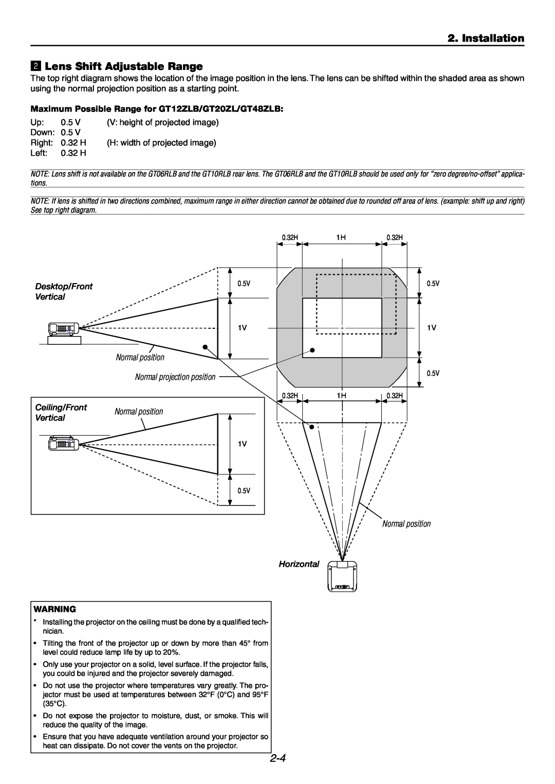
x Lens Shift Adjustable Range
c Optional Lens Installation
z Setting Up Your Projector
2. Installation
Screen Size and Projection Distance
Height
2. Installation
Throw distance
GT06RLB
Maximum Possible Range for GT12ZLB/GT20ZL/GT48ZLB
2. Installation x Lens Shift Adjustable Range
Desktop/Front
Vertical
Lens Shift Adjustable Range continued
2. Installation
Desktop/Front0.32V Vertical
Ceiling/Front
Before installation
2. Installation c Optional Lens Installation
e Secure the 4 screws using the hexagonal driver
2. Installation
For installing the GT12ZLB
2. Installation
SLOT1
2. Installation
For installing the GT06RLB
2. Installation
2-10
PC C
e Secure the 4 screws using the hexagonal driver
2. Installation
eSecure the 2 screws using the hexagonal driver
2-11
2. Installation
To adjust
2-12
When Viewing a DVI Digital Signal
2. Installation v Making Connections
Connecting Your PC or Macintosh Computer
Connecting to RGB 1 IN connectors BNC
Connecting an External Monitor
2. Installation
2-14
To connect SCART output RGB
Connecting Your DVD Player
2. Installation
2-15
DVD player
Connecting Your VCR or Laser Disc Player
2. Installation
2-16
VIDEO
Connecting to a Network
2. Installation
2-17
Example of LAN connection
2. Installation
Connecting the Supplied Power Cable
2-18
Basic Operation
Projecting an Image
z Turning on the Projector
3. Projecting an Image
Standby or Idle
Flashing for
Using the menu
c Adjusting the Picture Size and Position
3. Projecting an Image
x Selecting a Source
3. Projecting an Image
Tips on Adjusting Focus
v Correcting the Horizontal and Vertical
Keystone Distortion 3D Reform
3. Projecting an Image
When using the remote control or cabinet buttons
n Turning Up or Down Volume
3. Projecting an Image
b Optimizing RGB Picture Automatically
3. Projecting an Image
m Turning off the Projector
To turn off the projector
Convenient Features
z Turning Off the Image and Sound
4. Convenient Features
x Enlarging and Moving a Picture
c Getting the On-lineHelp and Information
v Using the USB Mouse
4. Convenient Features
b Using the USB HUB Function
Operate the PC mouse using the USB mouse
n Changing Background Logo
4. Convenient Features
m Making Freehand Drawings on a Projected
Image ChalkBoard
4. Convenient Features Lens Memory
Reference memory
Custom memory
Using the Viewer
z Making the Most out of the Viewer Function
playback
Features
5. Using the Viewer
z Making the Most out of the Viewer Function
Easy to use
When the tool bar is not displayed
5. Using the Viewer
Folder
x Operating the Viewer Function from the
Auto Play Mode
5. Using the Viewer
Viewing Digital Images
Preparations
5. Using the Viewer
Using the PC Card Files Fucntion PC Card Files
Deleting Captured Images
Using the Projector in a Network
6.Limitations of Warranty
6. Using the Projector in a Network
z END USER LICENSE AGREEMENT
1.Term
Contents of the Supplied CD-ROM
6. Using the Projector in a Network
Projector Easy Connection Settings
xIntroduction
when used
6. Using the Projector in a Network
Resolution
c Supported Projectors
v Equipment Connections and Settings
6. Using the Projector in a Network
When Using a Network Environment
Settings at the Projector Side
b Software Installation
6. Using the Projector in a Network
Installation
Uninstalling
n Starting/Exiting the Software
6. Using the Projector in a Network
Dynamic Image Utility
Start the Software
mTroubleshooting
6. Using the Projector in a Network
Check Points
Countermeasures
Check Points
6. Using the Projector in a Network
Countermeasures
Check Points
6-10
6. Using the Projector in a Network
Check Points
Countermeasures
6-11
6. Using the Projector in a Network
Check Points
Countermeasures
Setting Up for Double Stacking in Link Mode
7. Setting Up for Double Stacking in Link Mode
z Stacking and Connecting the Projectors
z-1.Assigning Projector IDs
Throw Distances for Optional Lenses
7. Setting Up for Double Stacking in Link Mode
Recommended Throw Distances for Double Stack
z-2.Stacking the Projectors
z-3.Hookup
7. Setting Up for Double Stacking in Link Mode
x Adjusting and Registering Signals to Be
7. Setting Up for Double Stacking in Link Mode
v Link Mode Setting
Projected
b List of Menu Items Available in Link Mode
7. Setting Up for Double Stacking in Link Mode
Using On-ScreenMenu
Using the Menus
8. Using On-ScreenMenu
z Basic Menu Operation
Customizing the Menu
x List of Direct Button Combinations
8. Using On-ScreenMenu
8. Using On-ScreenMenu c Menu tree
Advanced Menu Source Select Adjust Source Sound
8. Using On-ScreenMenu
Advanced Menu Source Select Adjust Source Sound
8. Using On-ScreenMenu
Using the Entry List
8. Using On-ScreenMenu
Entry Edit Command
v Menu Descriptions & Functions
Adjust Source
8. Using On-ScreenMenu
Video Adjust not available for RGB
YTR Adjustment
SweetVision
8. Using On-ScreenMenu
Split Mode
Deinterlace
Adjusting Color Temperature
8. Using On-ScreenMenu
Adjusting White Balance
Selecting Base Setting
Signal Level
8. Using On-ScreenMenu
Signal Type
Volume/Bass/Treble
Ref. Adjust
8. Using On-ScreenMenu
Using 3D Reform
8-12
Factory Default
8. Using On-ScreenMenu
All Data /Current Signal
Projector Options
8-14
8. Using On-ScreenMenu
Selecting Menu Display Time
Page
Setup
8. Using On-ScreenMenu
Page Setting Viewer Options Viewer Options
Setting Mouse Button and Sensitivity Mouse
Page Selecting Signal Format Signal Select
8. Using On-ScreenMenu
8-16
Selecting Operation Mode Operation Mode Select
8-17
8. Using On-ScreenMenu
Enabling Last Memory Last Memory
Page
Lamp Settings
8. Using On-ScreenMenu
8-18
Link Mode
8. Using On-ScreenMenu
8-19
LAN Mode
8. Using On-ScreenMenu
8-20
Advanced
8. Using On-ScreenMenu
WEP for Wireless only
8-21
8. Using On-ScreenMenu
8-22
Mail
Seamless Switch GT6000 only
8. Using On-ScreenMenu
2. Setting the Seamless Switch function
8-23
Setting a Password
8. Using On-ScreenMenu
8-24
Delete
8-25
8. Using On-ScreenMenu
Security
To register a PC card as a protect key
Timer
8. Using On-ScreenMenu
On/Off Timer
Tools
Enabling the On or Off Timer
8. Using On-ScreenMenu
Disabling the On or Off Timer
Deleting the On or Off Timer settings
Using Capture GT5000 only
8. Using On-ScreenMenu
Using PC Card Files
Using ChalkBoard
8-29
8. Using On-ScreenMenu
Projector Information
Test Pattern
x Replacing or Cleaning the Filter
Maintenance
c Cleaning the Cabinet and the Lens
z Replacing the Lamp
z Replacing the Lamp
9. Maintenance
To replace the lamp
Interlock
x Replacing or Cleaning the Filter
9. Maintenance
To clean the filter
To replace the filter
c Cleaning the Cabinet and the Lens
9. Maintenance
Appendix
z USB Memory Device or USB Memory Card
10. Appendix
Reader Support
10-2
Power Indicator
10. Appendix xTroubleshooting
Status Indicator
Lamp 1/2 Indicator
Problem
Common Problems & Solutions
10. Appendix
10-4
•Power on process for the projector and the PC
10. Appendix
10-5
10-6
10. Appendix cSpecifications
Model Number
GT6000/GT5000
10. Appendix
10-7
Mechanical
b Pin Assignments of D-SubRGB Input Connector
10. Appendix v Cabinet Dimensions
Mini D-Sub15 Pin Connector
10-8
10-9
10. Appendix n Compatible Input Signal List
10-10
10. Appendix m REMOTE 1 Connector
Pin No
SHORT/OPEN
PC Control Connector D-SUB9P
Using Software Keyboard
10. Appendix
PC Control Codes and Cable Connection
10. Appendix
⁄0Operation Using an HTTP Browser
10-12
Overview
10. Appendix
10-13
RGB1
NEC SOLUTIONS’ PROJECTOR PRODUCTS
LIMITED WARRANTY USA and Canada only
HOW LONG IS THE WARRANTY
WHAT IS COVERED AND WHAT IS NOT COVERED
DECLARATION OF CONFORMITY
Top
Page
Image
Contents