Chapter 1 | VisuaLink 128/384 Engineering Guide |
1.3 Physical/Electrical lnterface
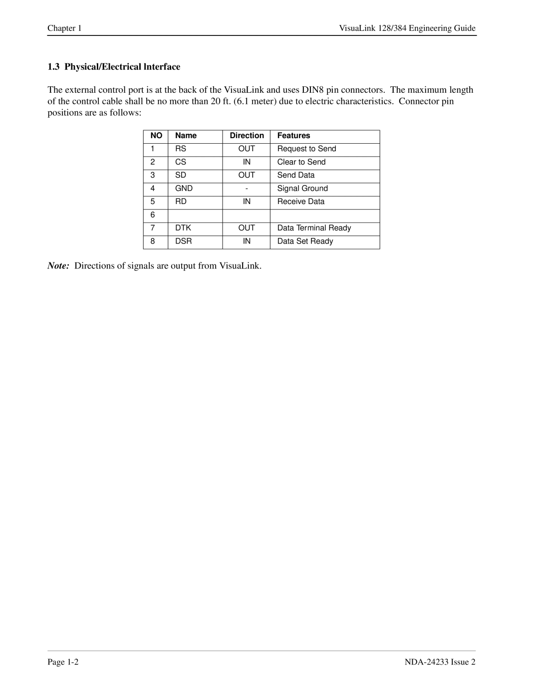
The external control port is at the back of the VisuaLink and uses DIN8 pin connectors. The maximum length of the control cable shall be no more than 20 ft. (6.1 meter) due to electric characteristics. Connector pin positions are as follows:
NO | Name | Direction | Features |
|
|
|
|
1 | RS | OUT | Request to Send |
|
|
|
|
2 | CS | IN | Clear to Send |
|
|
|
|
3 | SD | OUT | Send Data |
|
|
|
|
4 | GND | - | Signal Ground |
|
|
|
|
5 | RD | IN | Receive Data |
|
|
|
|
6 |
|
|
|
|
|
|
|
7 | DTK | OUT | Data Terminal Ready |
|
|
|
|
8 | DSR | IN | Data Set Ready |
|
|
|
|
Note: Directions of signals are output from VisuaLink.
Page |