3.4Adapter
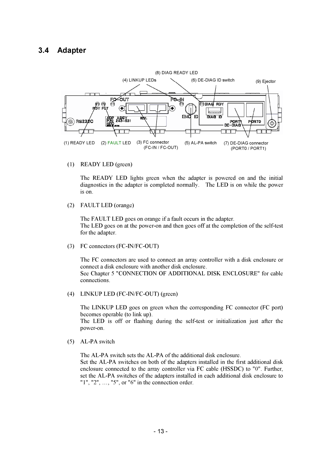
(8) DIAG READY LED
(4) LINKUP LEDs |
| (6) | (9) Ejector |
|
|
|
|
(1) READY LED (2) FAULT LED (3) FC connector | (5) |
(PORT0 / PORT1) |
(1)READY LED (green)
The READY LED lights green when the adapter is powered on and the initial diagnostics in the adapter is completed normally. The LED is on while the power is on.
(2)FAULT LED (orange)
The FAULT LED goes on orange if a fault occurs in the adapter.
The LED goes on at the
(3)FC connectors
The FC connectors are used to connect an array controller with a disk enclosure or connect a disk enclosure with another disk enclosure.
See Chapter 5 "CONNECTION OF ADDITIONAL DISK ENCLOSURE" for cable connections.
(4)LINKUP LED
The LINKUP LED goes on green when the corresponding FC connector (FC port) becomes operable (to link up).
The LED is off or flashing during the
(5)
The
Set the
-13 -