69
Appendix A
Technical specifications
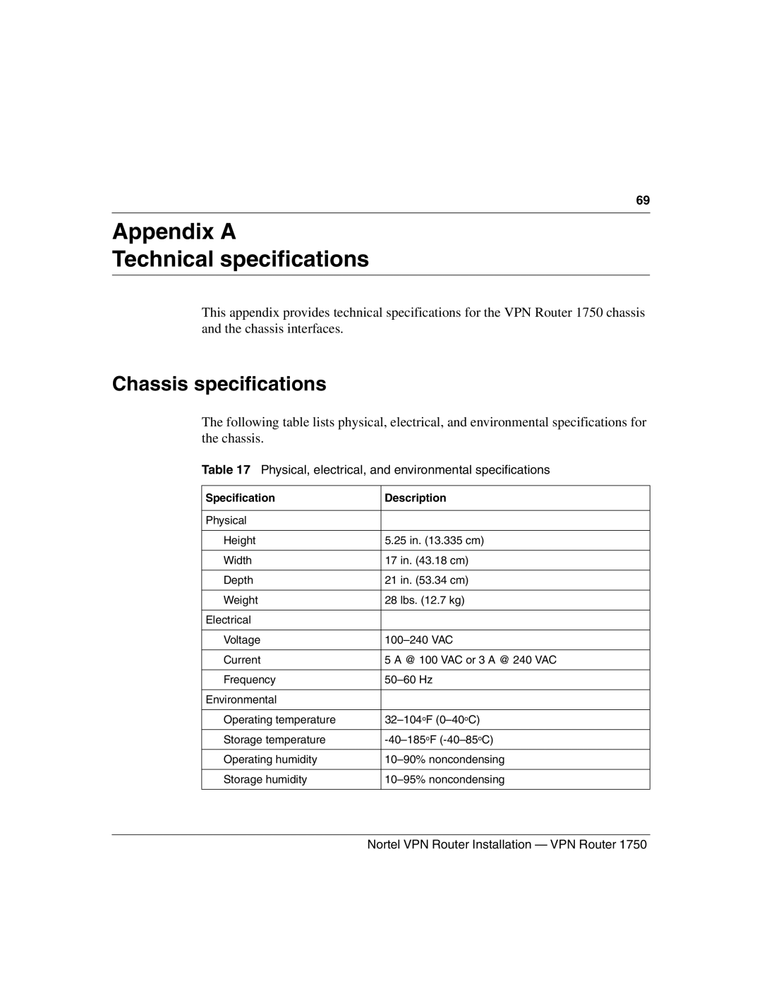
This appendix provides technical specifications for the VPN Router 1750 chassis and the chassis interfaces.
Chassis specifications
The following table lists physical, electrical, and environmental specifications for the chassis.
Table 17 Physical, electrical, and environmental specifications
Specification | Description |
|
|
Physical |
|
|
|
Height | 5.25 in. (13.335 cm) |
|
|
Width | 17 in. (43.18 cm) |
|
|
Depth | 21 in. (53.34 cm) |
|
|
Weight | 28 lbs. (12.7 kg) |
|
|
Electrical |
|
|
|
Voltage | |
|
|
Current | 5 A @ 100 VAC or 3 A @ 240 VAC |
|
|
Frequency | |
|
|
Environmental |
|
|
|
Operating temperature | |
|
|
Storage temperature | |
|
|
Operating humidity | |
|
|
Storage humidity | |
|
|