96Appendix A Technical specifications
Table 33 X.21 cable pinouts (continued)
Standard- |
|
| Standard- |
|
wired end |
| Pair number | wired end |
|
Signal name | and conductor | Notes | ||
|
|
|
|
|
1 | SHIELD | Pair 14A | 1 | At each end, the cable |
|
|
|
| shield and connector shell |
|
|
|
| must connect to pin 1 of the |
|
|
|
| connector. |
|
|
|
| Do not interconnect Shield |
|
|
|
| to Signal Ground because |
|
|
|
| these are separate signals. |
|
|
|
|
|
7 | SIGNAL GROUND | Pair 14B | 8 | Wires 13B and 14B |
|
|
|
| connect to pin 8 in the |
|
|
|
| |
|
|
|
| Do not interconnect Shield |
|
|
|
| to Signal Ground because |
|
|
|
| these are separate signals. |
|
|
|
|
|
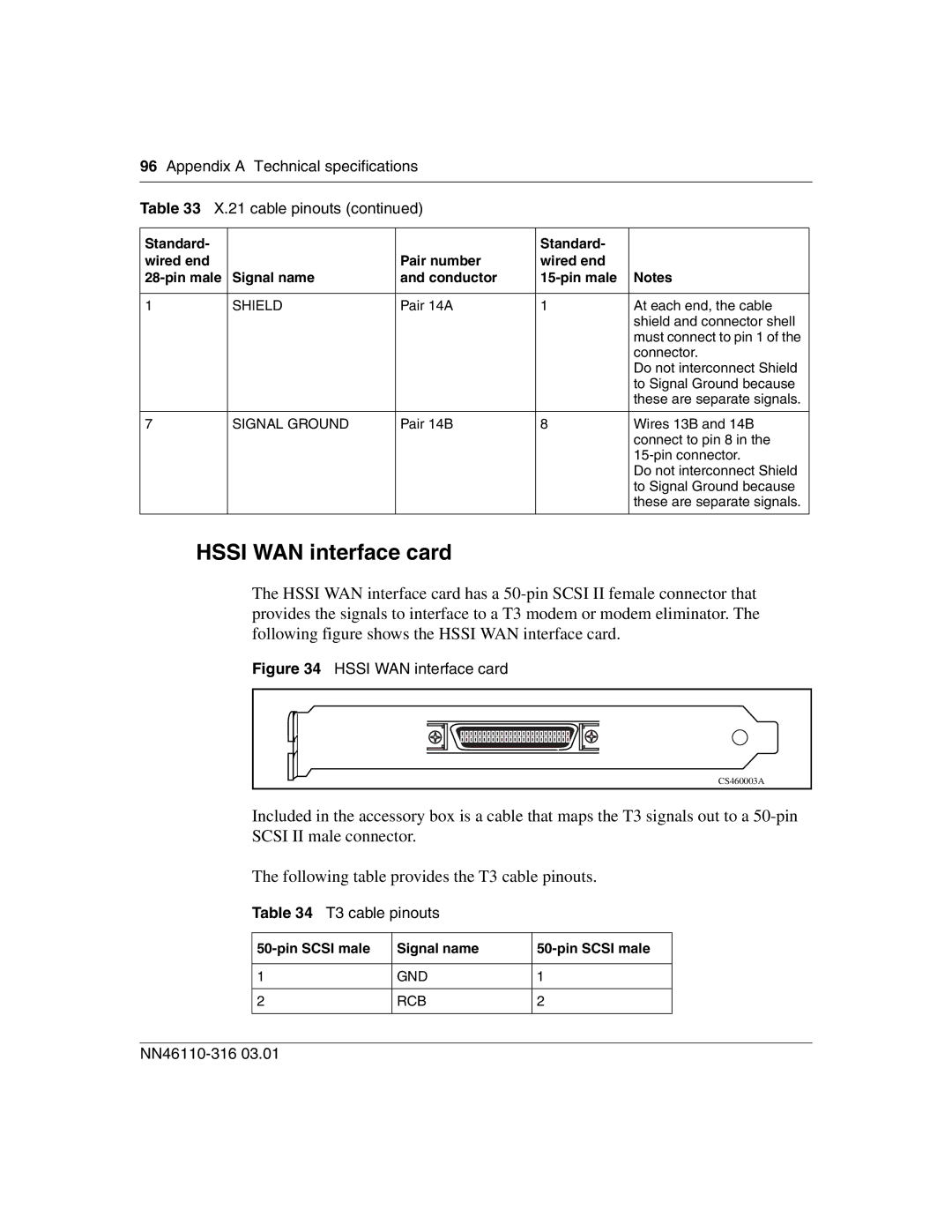
HSSI WAN interface card
The HSSI WAN interface card has a
Figure 34 HSSI WAN interface card
CS460003A |
Included in the accessory box is a cable that maps the T3 signals out to a
The following table provides the T3 cable pinouts.
Table 34 T3 cable pinouts
Signal name | ||
|
|
|
1 | GND | 1 |
|
|
|
2 | RCB | 2 |
|
|
|