88Appendix A Technical specifications
Use cable that is wired in accordance with
Connect the T1/E1 CSU/DSU WAN interface card to the service provider network by using a
•For a
•For a crossover connection, you cannot use a standard category 5 crossover cable. Do not interchange the T1/E1 CSU/DSU crossover cable and the Ethernet crossover cable.
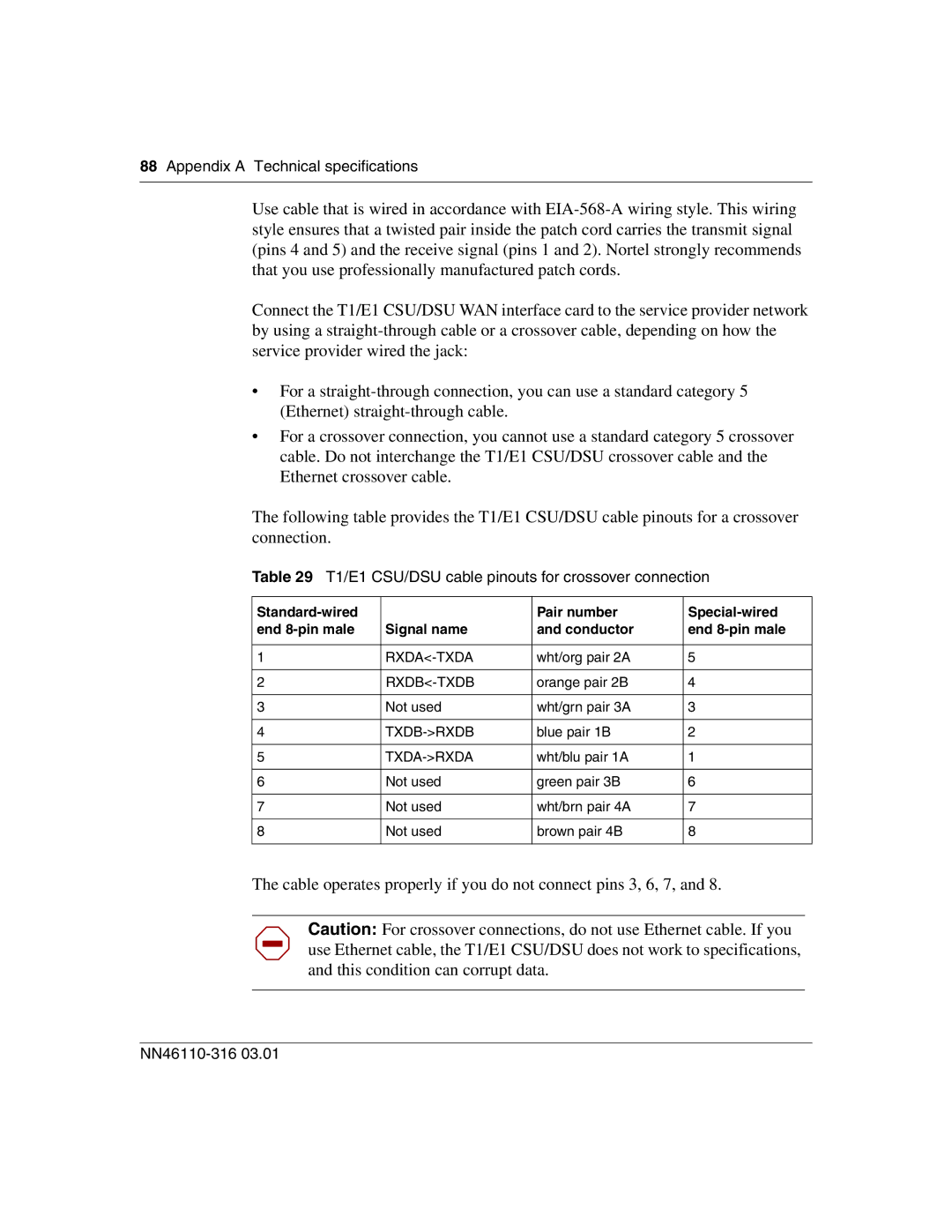
The following table provides the T1/E1 CSU/DSU cable pinouts for a crossover connection.
Table 29 T1/E1 CSU/DSU cable pinouts for crossover connection
| Pair number | ||
end | Signal name | and conductor | end |
|
|
|
|
1 | wht/org pair 2A | 5 | |
|
|
|
|
2 | orange pair 2B | 4 | |
|
|
|
|
3 | Not used | wht/grn pair 3A | 3 |
|
|
|
|
4 | blue pair 1B | 2 | |
|
|
|
|
5 | wht/blu pair 1A | 1 | |
|
|
|
|
6 | Not used | green pair 3B | 6 |
|
|
|
|
7 | Not used | wht/brn pair 4A | 7 |
|
|
|
|
8 | Not used | brown pair 4B | 8 |
|
|
|
|
The cable operates properly if you do not connect pins 3, 6, 7, and 8.
Caution: For crossover connections, do not use Ethernet cable. If you use Ethernet cable, the T1/E1 CSU/DSU does not work to specifications, and this condition can corrupt data.