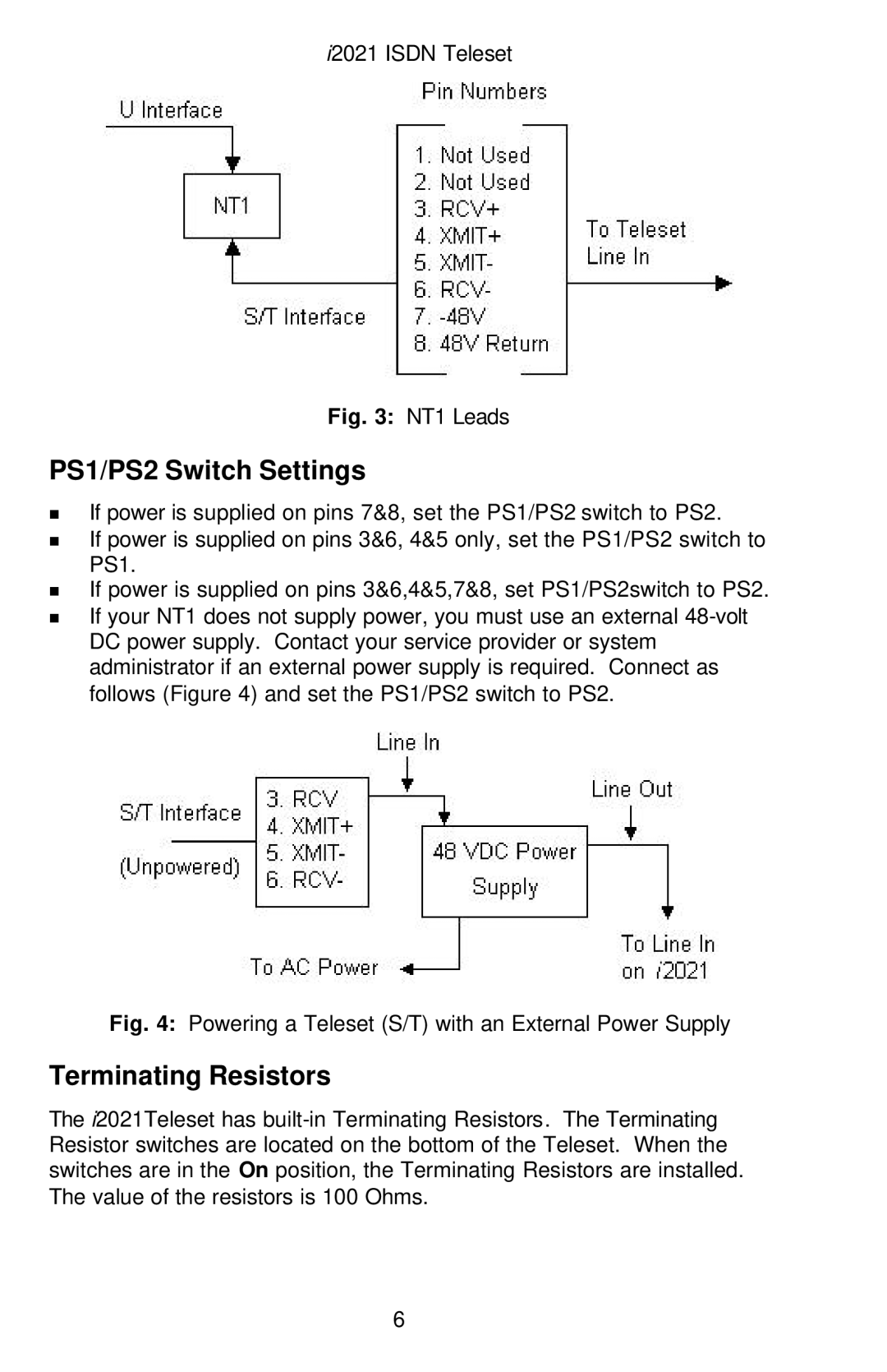
Nortel Networks i2021 Series manual PS1/PS2 Switch Settings, Terminating Resistors

Models: i2021 Series

1 77
Download 77 pages 33.91 Kb
Page 12
Image 12

i2021 ISDN Teleset

Fig. 3: NT1 Leads

PS1/PS2 Switch Settings

nIf power is supplied on pins 7&8, set the PS1/PS2 switch to PS2.

nIf power is supplied on pins 3&6, 4&5 only, set the PS1/PS2 switch to PS1.

nIf power is supplied on pins 3&6,4&5,7&8, set PS1/PS2switch to PS2.

nIf your NT1 does not supply power, you must use an external 48-volt DC power supply. Contact your service provider or system administrator if an external power supply is required. Connect as follows (Figure 4) and set the PS1/PS2 switch to PS2.

Fig. 4: Powering a Teleset (S/T) with an External Power Supply

Terminating Resistors

The i2021Teleset has built-in Terminating Resistors. The Terminating Resistor switches are located on the bottom of the Teleset. When the switches are in the On position, the Terminating Resistors are installed. The value of the resistors is 100 Ohms.

6

Page 12
Image 12
Nortel Networks i2021 Series manual PS1/PS2 Switch Settings, Terminating Resistors