Page: 78
Service Guide ML520/521
Chapter 3 Maintenance & Disassembly
3.2.09 Operator Panel PCB (LEOP)
1.Perform these procedures: 3.2.01 , 3.2.06
 , and 3.2.07
 .
.
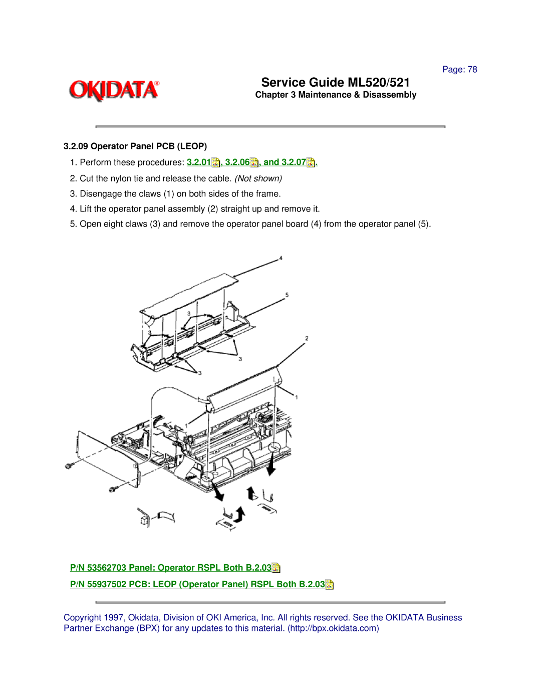
2.Cut the nylon tie and release the cable. (Not shown)
3.Disengage the claws (1) on both sides of the frame.
4.Lift the operator panel assembly (2) straight up and remove it.
5.Open eight claws (3) and remove the operator panel board (4) from the operator panel (5).
P/N 53562703 Panel: Operator RSPL Both B.2.03![]()
P/N 55937502 PCB: LEOP (Operator Panel) RSPL Both B.2.03![]()
Copyright 1997, Okidata, Division of OKI America, Inc. All rights reserved. See the OKIDATA Business Partner Exchange (BPX) for any updates to this material. (http://bpx.okidata.com)