Page: 52
Service Guide ML520/521
Chapter 2 Principles of Operation
2.2.03 Head Gap Mechanism
The head gap is automatically set for the thickness of the medium loaded in the printer. In the case of envelopes, where the medium thickness varies as the printhead moves along the platen, the strike force of the pins changes to compensate for the differences in thickness.
Head Gap Setting Operation
Once printing starts, the space motor rotates the ribbon gear, causing idle gear C to turn the change gear.
When the MPU requests a change in the head gap setting, the
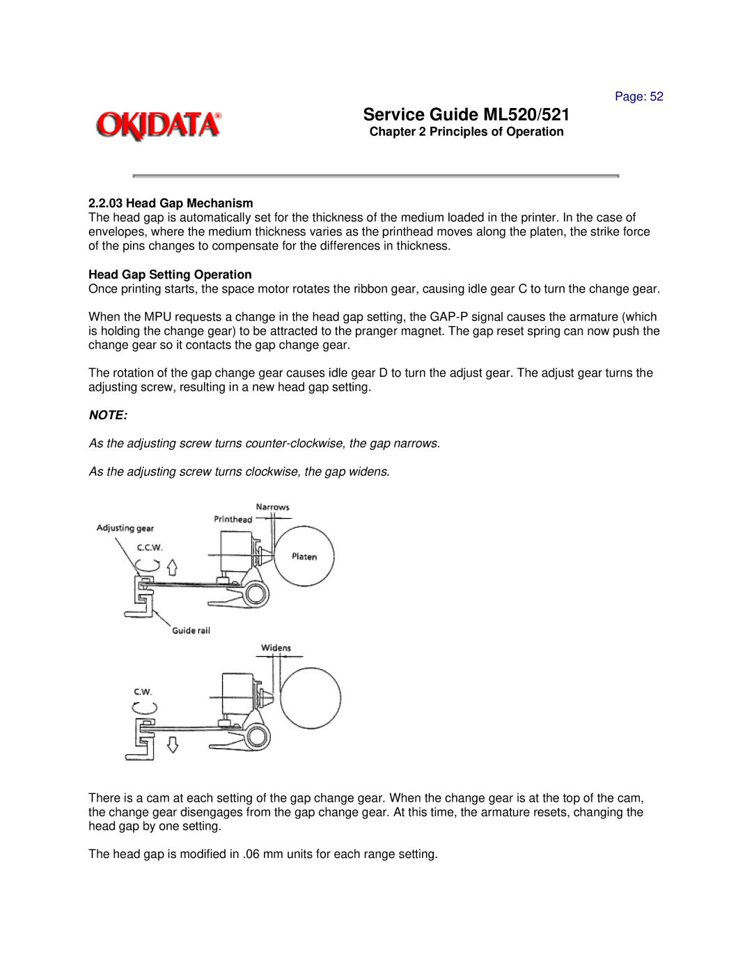
The rotation of the gap change gear causes idle gear D to turn the adjust gear. The adjust gear turns the adjusting screw, resulting in a new head gap setting.
NOTE:
As the adjusting screw turns
As the adjusting screw turns clockwise, the gap widens.
There is a cam at each setting of the gap change gear. When the change gear is at the top of the cam, the change gear disengages from the gap change gear. At this time, the armature resets, changing the head gap by one setting.
The head gap is modified in .06 mm units for each range setting.