Page: 83
Service Guide ML520/521
Chapter 3 Maintenance & Disassembly
3.2.14 Roller/Holder Backup Assembly
1.Perform these procedures: 3.2.01![]() , 3.2.02
, 3.2.02![]() , 3.2.04
, 3.2.04![]() , 3.2.10
, 3.2.10![]() , and 3.2.11
, and 3.2.11![]() .
.
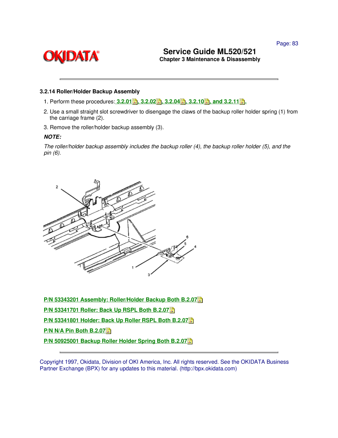
2.Use a small straight slot screwdriver to disengage the claws of the backup roller holder spring (1) from the carriage frame (2).
3.Remove the roller/holder backup assembly (3).
NOTE:
The roller/holder backup assembly includes the backup roller (4), the backup roller holder (5), and the pin (6).
P/N 53343201 Assembly: Roller/Holder Backup Both B.2.07![]()
P/N 53341701 Roller: Back Up RSPL Both B.2.07![]()
P/N 53341801 Holder: Back Up Roller RSPL Both B.2.07![]()
P/N N/A Pin Both B.2.07![]()
P/N 50925001 Backup Roller Holder Spring Both B.2.07![]()
Copyright 1997, Okidata, Division of OKI America, Inc. All rights reserved. See the OKIDATA Business Partner Exchange (BPX) for any updates to this material. (http://bpx.okidata.com)
