OMB-483-0901 Rev
Portable Data Recorder
For immediate technical or application assistance
Servicing North America
Servicing Europe
Appendices
How To Use This Manual
Table of Contents
EZ-PostView and ViewXL Calibration
ChartScan User’s Manual
Overview
ChartScan Unit Startup and ChartView Tutorial
Inspect Your System
Unit Startup
Verify DIP Switch Setting
Verify Voltage Setting
Install Signal Conditioning Cards
Selection Micro Setting Switch #
Connect Expansion Chassis option
Install Ieee 488 Interface Communications Card option
Error Condition LED Indicators
Apply Power to ChartScan
DB50 Pin Descriptions
Start ChartView, Configure System, and Collect Data
� = Mouse, Ú= Arrow Keypads , � = PageUp/PageDown Keypads
ChartView Main Window Control Options
Device Interface
Configuration Files
ChartView, Basic Concepts
Acquiring Data with no charting or meter use
ChartView Tutorial
Select Interface Device
Advanced
Moderate
Configure Channels & Alarms
Configure Acquisition
Parameter Options
High Speed Setup
Stop
Count
Review Configuration
Page
ChartScan User’s Manual
General Description
General Information
Data Handling and Triggering
Operational Aspects
Software and Hardware
ChartScan Specifications
Channels
General
Data Storage & Format
Triggers
Digital I/O Interface & Alarms
Calibration
− Notes
Front Panel
Hardware
Rear Panel
Changing the Voltage Setting
Power Aspects
Replacing the AC Power Supply Fuse
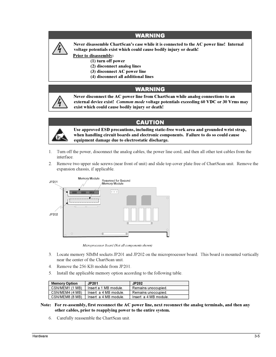
Memory Configuration
Expanded Memory Options
Memory Option JP201 JP202
Calibration Memory Write Enable/Disable
RS-232/422 Interface Configurations
Configuring RS-232/422 Parameters
Standard Units, Only
Selection Micro Setting Switch
Early Production Units, Only
ChartScan to PC Connection RS-232 DB9 Male Pin & Signal
Serial Port Pin Connectors
Cable Wiring DB9 Female Pin & Signal
Pin # RS-232 Signal Pin Description
Ethernet Interface Configuration
Specifications
Ieee 488 Interface Configuration Option
Ieee 488 Pinout
Ieee 488 Configuration
Ieee 488 Configuration Settings
Logic Levels
Digital I/O Lines
Digital I/O Port Pinout
Signal Conditioning Cards
External TTL BNC Connectors
Temperature Range, Accuracy, and Resolution1 Type J
Input Connector
Temperature Units
Fault Detection
Digital Filtering
Voltage Range2, Accuracy3 and Resolution
CSN14/LV/ T, B, & S Low Voltage Cards
Voltage Range, Accuracy1 and Resolution
Voltage Range, Accuracy and Resolution
Input Connectors
Number of Inputs
Slot
Device
Connecting the Expansion Chassis
CSN/Relay Card Specifications
Expansion Chassis, CSN/Exp Option
Cross Section of Mounting Block
Device Channel Assignments Slot
Automatic Channel Assignment
Number of Slots Four
Channel-to-System Isolation 500 V peak Dimensions
− Notes
ChartView Software Reference
Three Ways of Using ChartView
Groups, Charts, & Channels
Waiting for Trigger
What ChartView and ChartView Plus Provide
Main Window
ChartView Main Window and Control Options
Channel Information Region
Instrument
Status Indicator Region
Main Window Toolbar
Start, Pause, Stop Charts
Group Select
Scroll Faster Scroll Slower
Normal Edit
Display Configuration
ChartView Software Reference ChartScan User’s Manual
Adjusting Channel Setup for Channel
Manually Creating a Display
Adding a Chart to Group
Adjusting Channel Setup for Channel
PostView post-acq data viewer
Channel Configuration
Arm Acquisition
Disarm
Main Window Pull-Down Menus
Print Charts
File
See File Menu Note, immediately following this text
File Menu Note
Chart
View
Display config
System
Charts
Acquisition
Data
Acquire
Displays the condition of a data acquisition
Ctrl + J manual control
Command Characters Data Destination Timeout Region
Ctrl + U manual
Window
Setup
Device …
Log configuration
ChartScan User’s Manual ChartView Software Reference
Device Expanded Menu obtained with use of the F12 Key
Log Enable
Ctrl+A
Bar Graph, Analog, and Digital Meters
Setup
Overview
Bar Graph Meters
Configuration Note
…. for Analog Meters
Analog Meters
…. For Digital Meters
Digital Meters
Meter Toolbars
Reset. This feature does not apply to the Digital Meters
Meter Pull-Down Menus
Name Function
Configuring a Meter
Meters Configuration Menu
Channel & Alarm Setup Dialog Box
Setup Window
Configure Meter Settings, Function Descriptions
Channel and Alarm Setup, Button Descriptions
Example
Channel Configuration Columns
Alarm Configuration Columns
Acquisition Setup Dialog Box
Acquisition Setup Dialog Box, Normal Mode
Normal Mode, CH1 and CH2 Assigned to a Chart
Burst Mode, Operational Issues
Introduction
Measuring AC Voltage, or AC RMS Voltage
Measuring AC RMS
Data Destination
Data Destination Dialog Box
Why use Auto Re-arm?
Introduction
Chart Setup Wizard
Chart Setup Wizard, Simple Mode
Automatic Chart Setup with Wizard
Bypassing Automatic Chart Setup
EZ-PostView
Introduction
ViewXL
EZ-PostView includes the following features
Reference Note
Range 100 mV
Calibration Setup
Range
Hardware Protected RAM
Non-Volatile Storage of Calibration Constants
ScanCal Software Application
Using ScanCal
ScanCal’s Main Window
Instruction Tool Icon
System Inventory
Interface Parameters
Mode Indicator
Password
Command Active Indicators
Calibration Without ScanCal
Offset Calibration of Main Unit
Calibration of Main Unit
Required Equipment
U129
U128
U130
U132
Gain Calibration of Main Unit
U128
Offset Calibration of Cards
Calibration of Signal Conditioning Cards
Cal Err offset, gain, or temperature sensor out of range
Gain Calibration of Low Volts Cards
ChartScan User’s Manual Calibration
#1X QC?
…to clear the buffer
C1,1X
Volts DC Slot #
Gain Calibration of High Volts Cards
…to clear the buffer
Option a Cold Cell Method
Cold Junction Calibration
Option b Hot Cell Method
Option c T/C Calibrator/Simulator Method
Calibration ChartScan User’s Manual
Enter J3,3,0000.0X J6,3,0000.0X J11,3,0000.0X J14,3,0000.0X
Calibration ChartScan User’s Manual
Appendices
ChartScan User’s Manual
Appendix a
Contents
Command Syntax
Conflict Errors
Command Interpretation
Immediate & Deferred Commands
Fixed Formats
Command Type
Order Function
Deferred Commands, Order of Execution
Command Summary
E000
#make
E001
E002
Level
Lchan
Hyst Chan max
Mmask
#chans
Rtype
Stime
Tstart
− Notes
Command Description Format
Command Reference
Commands
Type
PRINT#1, OUTPUT07T1,1,0,0X
Trigger On Command
PRINT#1, OUTPUT07 @X
Sleep
PRINT#1,SPOLL07
Flush Acquisition Buffer
INPUT#2, S%
PRINT#1,OUTPUT07 *BX
‘ Clear all channels configuration
Clear Channel Configuration
PRINT#1,OUTPUT07
Channel
PRINT#1,OUTPUT07Q?T?Y?X
Restore Factory Settings
PRINT#1,ENTER07
Input A$
Change Calibration Keyword
If C% and 16 then PRINT,ERROR-INVALID Keyword Sleep
PRINT#1, OUTPUT07U2X
PRINT#1, ENTER07 INPUT#2, C%
PRINT#1,OUTPUT07K12345X
Adjust Calibration Card Pots
PRINT#1,OUTPUT07*P02X
PRINT#1,OUTPUT07*P01X
PRINT#1,OUTPUT07*RX
Power-On Reset
While S% and 4 =
Print #1, SPOLL07
‘ Screen shows Q1,7,7,7,0 T1,3,0,0 Y000100
Power-Up Settings
PRINT#1,OUTPUT07*S1X
PRINT#1, OUTPUT07*RX
PRINT#1,OUTPUT07*T1X
Time Stamping
PRINT#1,OUTPUT07*T2X
PRINT#1,OUTPUT07*T0X
Assign Alarm Output
PRINT#1,OUTPUT07A#1X
# Alarm Stamping
PRINT#1,OUTPUT07A#0X
Byte 1 A07 A00 Byte 2 A15 A08 Byte 3 A23 A16 Byte 4 A31 A24
Configure Channels
Thermocouple Card Types
Same as Without temperature Temp
These special types are valid only in degrees Celsius
Volts Card Types
PRINT#1,OUTPUT07X
PRINT#1, OUTPUT07*C
PRINT#1,OUTPUT07 U13X
# Select Card
PRINT#1, OUTPUT07M#0X
Set Relay Make Time
PRINT#1, OUTPUT07W#32X
PRINT#1, OUTPUT07D#12X
PRINT#1, OUTPUT07H17X
End Calibration Mode
PRINT#1, OUTPUT07G17,1X
PRINT#1, OUTPUT07J1,2,90.0X
PRINT#1,CLEAR07
? Error Status Query
PRINT#1,OUTPUT07E?X
PRINT#1,ENTER07 INPUT#2,A$ Print A$
Data Input Formats see Note
Set Data Format
MM/DD/YY
Data Output Formats
Dddddddd
Dddddddd =
PRINT#1,OUTPUT07C1, 1
PRINT#1, OUTPUT07F0,0X
PRINT#1, OUTPUT07 U4X
PRINT#1, ENTERO7
PRINT#1
# Set Burst Mode Frequency
OUTPUT07F#15000.0X
OUTPUT07F#100.5X
PRINT#1, OUTPUT07G17,1
Calibrate Channel Gain
Calibrate Channel Offset
Inorm
Set Scan Interval
Acq
PRINT#1, OUTPUT07I010000.0
PRINT#1, OUTPUT07I#0X
Digital Input Stamping
PRINT#1, OUTPUT07R1X
PRINT#1, OUTPUT07I#1X
Temp
Calibrate Cold Junction Offset
PRINT#1, OUTPUT07J1,2,101.7X
PRINT,ERROR-INVALID Keyword Halt
Enter Calibration Mode
Print #1, ENTER07 INPUT#2, C%
If C% and 16 then
Hyst
Set Trigger Level
PRINT#1, OUTPUT07F0,0X PRINT#1, OUTPUT07L1,100.0,10.0X
PRINT#1, OUTPUT07T4,5,0,0X
Set SRQ Mask
PRINT#1, OUTPUT07M#1X
Set Measuring Mode
Set Event Mask
PRINT#1 OUTPUT07O?X
Set Digital Outputs
Line Input #2, N$ Print N$
PRINT#1, OUTPUT07O?X
Program Trigger Times
OUTPUT07 V1 X V?
? Query
PRINT#1, OUTPUT07 V0 X V?
PRINT#1, OUTPUT07 V4 V?
CR LF/EOI LF CR/EOI USER/EOI User
Set Query Terminator
Terminator Type Terminator Description IEEE-488
None
U4X U5X
R1X R2X R3X
PRINT#1,OUTPUT07F0,0X
PRINT#1,OUTPUT07Q?X
PRINT#1, OUTPUT07 C#5X
QC? Query Card Data
PRINT#1, OUTPUT07 QC?X
INPUT#1 PRINT#1
API Commands Appendix a
While S% and 8 =
Read Buffered Data
PRINT#1 SPOLL07 INPUT#2, S% Wend PRINT#1,OUTPUT07R1X
PRINT#1,ENTER07 Line INPUT#2, A$
PRINT#1,OUTPUT07F1,0X
# Read Last Readings
PRINT#1,OUTPUT07R#16X
Line Input #2, R$ Print R
PRINT#1, OUTPUT07 S140000.0,4/30/93X
Set Real Time Clock
Set Trigger Configuration
000100.0X
PRINT#1, OUTPUT07
PRINT#1, OUTPUT07Y100,10000,0X
PRINT#1, OUTPUT07T1,7,0,1X
User Status
?I?L?P?Q?S?T?Y?
01024
00256
001,1,002,0,003,0 …
#123101.20,04/24/93
Change Calibration Keyword
PRINT#1, OUTPUT07V44X
Set User Terminator
PRINT#1,OUTPUT07@X
PRINT#1, OUTPUT07V58X
PRINT#1, OUTPUT07W#64X
# Set Average Weight
OUTPUT07Y0,10,0X
PRINT#1, OUTPUT07C1
PRINT#1,OUTPUT07*C
Execute
PRINT#1,OUTPUT07C1-16,1 C17,2
C18-32,3
PRINT#1,OUTPUT07N0 N2
Set Counts, or Select Blocks
PRINT#1,SPOLL07 INPUT#2,S% Wend PRINT#1,OUTPUT07N0 N1
PRINT#1,SPOLL07 INPUT#2,S% Wend PRINT#1,OUTPUT07U6X
Appendix B
Memory Allocation
U16
Measuring Modes
U17
‘Select Normal mode #16 Samples over which to average
Normal Mode
‘Select Normal mode Sample over which to average
Scan time = #channels x #samples/channel + 12 x 520.83 µs
‘Select high-speed, single-channel mode
High-Speed, Single-Channel Mode Burst Mode
Condition
PRINT#1,OUTPUT07 U4X
Configuration Requirements
Signal-Conditioning Modules Type Inputs Connector
Channel Configuration
CSN14/LV/ T, B, or S Configuring Low Volts Channels
CSN14/TC/P Configuring Thermocouple Channels
Type Volts DC
Type Volts AC
CSN14/HV/S Configuring High Volts Channels
Scan Configuration
Configuring a Scan
Configuring the Scan Interval
Component Description Required
Acquisition Configuration
I000010.0,000000.1
I000010.0,000000.0
Continuous, Gap-Free Acquisition with Two Timebases
Pre-Trigger State
Configuration Aspects for Programmers Appendix B
Post-Trigger State
Trigger and Stop Events
Post-Stop State
Alarm on or off
Selected Temperature Channel High or Low Level
External TTL High or Low Level
‘@’ character
Time Stamping *T
Alarm Stamping A#
Digital Input Stamping I#
With Alarm Stamping
PRINT#1, OUTPUT07A#1X
With Digital Input Stamping
‘ Enable digital input stamping
Trigger Block Organization
Acquisition Buffer, a Description
PRINT#1,ENTER
Get the response
PRINT#1,OUTPUT 07 U6X
PRINT#1,OUTPUT 07R1X
Multiple Trigger Blocks
Acquisition Buffer Interrogation
Field Response Implication
Field Response Implication
PRINT#1,OUTPUT07 U6X
Reading the Acquisition Buffer
Input
Print
PRINT#1,OUTPUT07R3X
PRINT#1,OUTPUT07R2X
Alarm Set Points
Configuring Alarms
Digital Alarm Outputs
Print #1
Set Point Hysteresis
PRINT#1,OUTPUT07A3,0X ‘Disable channel 3 from digital output
Digital I/O Operation
Appendix C
HLL Register Contents
Using High/Low/Last HLL Registers
Accessing HLL Registers
Example
Example shows how to read only the Last readings
Data Input Formats
Data Format F
Code
Data Format F
Engineering Units Data Format
Data Output Formats
Examples
Thermocouples
Time/Date Stamp
Volts
Hhmnss.t,mm,dd,yy
Counts Data Format
Binary Data Format
010203.5
HHhmstMDYLLhmstMDYll
Configuring Power-Up State
Status Commands
Query ? Commands
Vuser where 0 user
Queries
Status, Event Reporting, and Mask Registers
Register Access
Register Chart Status and Event Reporting Registers
Register Chart Mask Registers
Theory of Operation
Appendix C Registers, Data Formats, & Queries
Error Source Register E? Command
Calibration Status Register U2 Command
Event Status Enable Register
Event Status Register
Bit Location Value Description
Status Byte Register
Ieee 488 Serial Poll Response
Service Request Enable Register
DIO8 MSBit
DI02
Using Status Reporting Registers
Trigger Overrun
Trigger Latency
Buffer Overrun
Avg
Real Time Clock
Open Thermocouple/Range Error Checking
Buffer Overrun With One Trigger Block
Buffer Overrun With Multiple Trigger Blocks
− Notes
Appendix D
ChartScan Program Examples
Reading HLL Data from T/C & Volts Cards using HLL32.BAS
Reading HLL Status using HLL16.BAS
Print #1, Output 07C1-16,1X Print #1, Output 07C17-32,2X
CLS Print The ChartScan is resetting
Print #1, Output 07Y30,1,200X
Print #1, Output 07I000001.0,00000.3X
PRINT#1, Enter INPUT#2, READING$
While INKEY$ = ‘’
Print #1, ENTER07 Output #2, U%
Print #1, Output 07Y50,100,200X
Print #1, Output 07C1-16,3X Print #1, Output 07C17-32,2X
Print #1, Output 07I000000.1,000000.1X
Print #1, Output 07L1,20.0,0X T4,5,0,0X
Operating Alarms using ALARM2.BAS
Else
Print #1, Enter 07 Line Input #2, A$ Print A$
END if
END if Wend
On PEN Gosub AlarmHandler
Using the Ieee 488 SRQ with Alarms using ALAR2SRQ.BAS
PEN on Print #1, ARM SRQ
Print #1, Output 07M1X
Locate
Collecting Data in Binary Format using BINACQ.BAS
Input #2 Print #1 Output 07O?X
Line Input #2, A$
Print #1, Output 07R2X
Print #1, Enter 07 Line Input #2, U$ Print U$
Binary DATA%/10 = C
Print #1, Clear Print #1, Output 07*S1X
Collecting Binary-Formatted HLL Data using BINHLL.BAS
Print #1, Output 07M#0X Print #1, Output 07W#32X
Print #1, Output 07C1-16,1X Print #1, Output 07C17-32,14X
Print STR$VALLAST$ Else
Decode received data and print on screen in Ascii
Print #1, Output 07I000000.3,000000.0X
Print #1, Output 07Y1000,20,10X
Print #1, Output 07T1,8,1,0X
Print #1, Output 07Q,0,0,8,8,0X
Loop Until UA$=
Print #1, Output 07U6X
Print UAT$
Print UA$
Wend Close END
While INKEY$ =
Print #1, Disarm SRQ
Print UA
Input #2, EVENT%
Print #1, Output 07R3X
Sleep Print #1, ARM SRQ Return
Print #1, Output 07C1,14x
Print #1, Output 07M#1X Print #1, Output 07F#20000.0X
Print #1, Output 07Y0,8,0X
For i = 1 to UA% Print #1, Enter
Print #1, Output 07V32X Q7,0,7,7,1X
Locate 14, 1 Print Scan i is
Print SCAN$
Appendix E
− Notes
Appendix F
Universal Command Group UCG
Decimal Values 00 to 63 ACG, UCG & LAG
Box Items
$41
Decimal Values 64 to 127 TAG & SCG
Ascii Code Details
Decimal Values 00 to 31 ACG & UCG Characteristics
Decimal Values 00 to 31 ACG & UCG Descriptions
Dec Name Description Addressed Command Group ACG
Ascii Control Codes 00 to
Space
Decimal Values 32 to 63 LAG
Decimal Values 64 to 95 TAG
Decimal Values 96 to 127 SCG
Delete Command
DEL
Ascii Code SummaryAppendix F
− Notes
Appendix G
LED Indications of Error Conditions LED Indicators
ChartScan Error Messages
Appendix H
Abbreviations Appendix H
Index
ChartScan User’s Manual
WARRANTY/DISCLAIMER
Temperature