Appendix C

Registers, Data Formats, & Queries


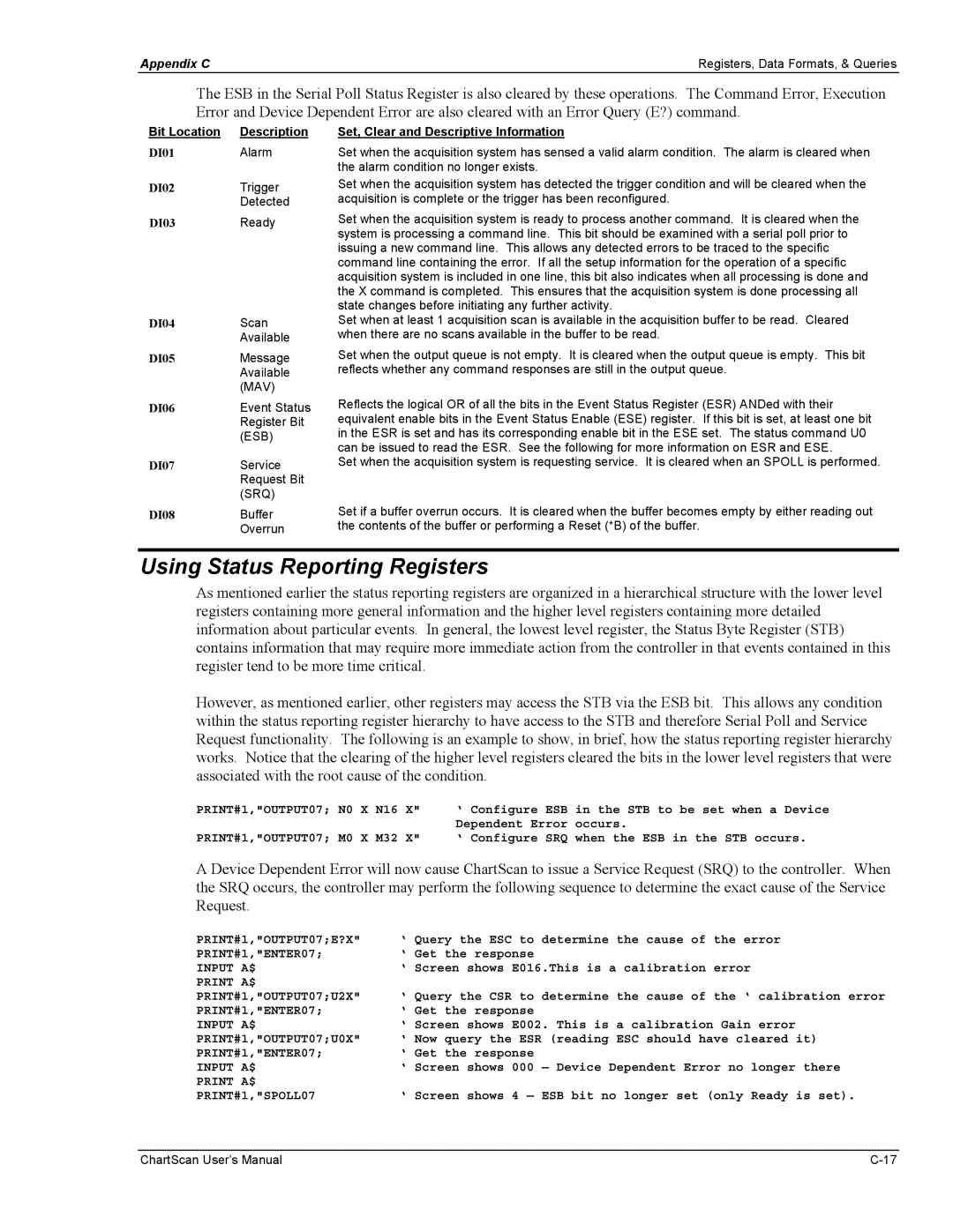
The ESB in the Serial Poll Status Register is also cleared by these operations. The Command Error, Execution Error and Device Dependent Error are also cleared with an Error Query (E?) command.

Bit Location

Description

Set, Clear and Descriptive Information

DI01

Alarm

Set when the acquisition system has sensed a valid alarm condition. The alarm is cleared when


the alarm condition no longer exists.

DI02

Trigger

Set when the acquisition system has detected the trigger condition and will be cleared when the


Detected

acquisition is complete or the trigger has been reconfigured.

DI03

Ready

Set when the acquisition system is ready to process another command. It is cleared when the


system is processing a command line. This bit should be examined with a serial poll prior to


issuing a new command line. This allows any detected errors to be traced to the specific


command line containing the error. If all the setup information for the operation of a specific


acquisition system is included in one line, this bit also indicates when all processing is done and


the X command is completed. This ensures that the acquisition system is done processing all


state changes before initiating any further activity.

DI04

Scan

Set when at least 1 acquisition scan is available in the acquisition buffer to be read. Cleared


Available

when there are no scans available in the buffer to be read.

DI05

Message

Set when the output queue is not empty. It is cleared when the output queue is empty. This bit


Available

reflects whether any command responses are still in the output queue.

(MAV)

DI06

Event Status


Register Bit


(ESB)

DI07

Service


Request Bit


(SRQ)

DI08

Buffer


Overrun

Reflects the logical OR of all the bits in the Event Status Register (ESR) ANDed with their equivalent enable bits in the Event Status Enable (ESE) register. If this bit is set, at least one bit in the ESR is set and has its corresponding enable bit in the ESE set. The status command U0 can be issued to read the ESR. See the following for more information on ESR and ESE.

Set when the acquisition system is requesting service. It is cleared when an SPOLL is performed.

Set if a buffer overrun occurs. It is cleared when the buffer becomes empty by either reading out the contents of the buffer or performing a Reset (*B) of the buffer.

Using Status Reporting Registers

As mentioned earlier the status reporting registers are organized in a hierarchical structure with the lower level registers containing more general information and the higher level registers containing more detailed information about particular events. In general, the lowest level register, the Status Byte Register (STB) contains information that may require more immediate action from the controller in that events contained in this register tend to be more time critical.

However, as mentioned earlier, other registers may access the STB via the ESB bit. This allows any condition within the status reporting register hierarchy to have access to the STB and therefore Serial Poll and Service Request functionality. The following is an example to show, in brief, how the status reporting register hierarchy works. Notice that the clearing of the higher level registers cleared the bits in the lower level registers that were associated with the root cause of the condition.

PRINT#1,"OUTPUT07;

N0

X

N16

X"

‘ Configure ESB in the STB to be set when a Device


Dependent Error occurs.

PRINT#1,"OUTPUT07;

M0

X

M32

X"

‘ Configure SRQ when the ESB in the STB occurs.

A Device Dependent Error will now cause ChartScan to issue a Service Request (SRQ) to the controller. When the SRQ occurs, the controller may perform the following sequence to determine the exact cause of the Service Request.

PRINT#1,"OUTPUT07;E?X"

‘ Query the ESC to determine the cause of the error

PRINT#1,"ENTER07;

‘ Get the response

INPUT A$

‘ Screen shows E016.This is a calibration error

PRINT A$


PRINT#1,"OUTPUT07;U2X"

‘ Query the CSR to determine the cause of the ‘ calibration error

PRINT#1,"ENTER07;

‘ Get the response

INPUT A$

‘ Screen shows E002. This is a calibration Gain error

PRINT#1,"OUTPUT07;U0X"

‘ Now query the ESR (reading ESC should have cleared it)

PRINT#1,"ENTER07;

‘ Get the response

INPUT A$

‘ Screen shows 000 — Device Dependent Error no longer there

PRINT A$


PRINT#1,"SPOLL07

‘ Screen shows 4 — ESB bit no longer set (only Ready is set).

ChartScan User’s Manual

C-17

Page 234
Image 234
Omega Vehicle Security 1400 manual Using Status Reporting Registers, DI02

1400 specifications

The Omega Vehicle Security 1400 stands out as a premier solution for vehicle protection, offering a blend of advanced technology and user-friendly features. With the increasing rise of vehicle thefts, incorporating a robust security system has become essential for vehicle owners. The Omega 1400 aims to address these concerns effectively, ensuring peace of mind for users.

One of the key features of the Omega Vehicle Security 1400 is its sophisticated alarm system. The device is equipped with a motion sensor that activates the alarm when unauthorized movement is detected. This feature provides an added layer of protection, alerting owners to potential threats even when they are away from their vehicles. Additionally, the system comes with multiple sensors that monitor doors and trunk openings, fortifying security against tampering.

A standout component of the Omega 1400 is its remote control functionality, which allows users to arm and disarm the alarm with ease. Featuring a user-friendly remote, drivers can secure their vehicles from a distance, ensuring convenience and accessibility. The remote not only operates the alarm system but also integrates a panic button, which can be used in emergency situations to deter potential threats.

The Omega Vehicle Security 1400 is also designed with cutting-edge technology, offering compatibility with smartphone applications. This innovation enables users to monitor their vehicles in real-time, providing alerts directly to their mobile devices. Users can check the status of their vehicle, adjust settings, and receive notifications if the alarm is triggered, ensuring they are always connected to their vehicle's security.

Another remarkable characteristic of the Omega 1400 is its built-in GPS tracking capability. In the unfortunate event of a theft, the GPS feature allows vehicle owners to track the location of their vehicle, increasing the chances of recovery. This technology proves invaluable for users who prioritize the safety of their assets.

Additionally, the Omega Vehicle Security 1400 supports a robust battery backup system. This ensures that the alarm remains functional even if the vehicle's power supply is compromised. The reliability and durability of this security system make it a worthy investment for anyone looking to safeguard their vehicle.

In summary, the Omega Vehicle Security 1400 brings together advanced alarm technologies, remote access, GPS tracking, and reliable power support, creating a comprehensive security solution tailored for modern vehicle owners. Each feature has been designed with user convenience and vehicle protection in mind, making it a top choice in the vehicle security landscape.