System Configuration
composite video output when a receiver that is capable of displaying a component signal is not available.
In most cases you will want to have the conver- sion circuitry engaged, but in some installations it may be preferable to turn it off. If you prefer the way a video signal looks in its original form, you may turn the video conversion circuitry off by first making certain that the IN/OUT SETUP menu (Figure 2) is on the screen, and then press- ing the ⁄/¤ Navigation Button Euntil the
➞cursor is pointing to VIDEO CONV and then press the ‹/› Navigation Button Eso that OFF is shown in highlighted video. This set- ting is made individually for each input, so be cer- tain to make any desired change for each input source where you wish to turn the conversion cir- cuitry off.
Should you wish to return the conversion circuitry to the On position at any time, simply use the steps shown above, but press the ‹/› Navigation Button Eso that ON is shown in highlighted video.
The final input setting is also individual to each input, and it allows you to set the priority for the video conversion circuitry. In most cases, where only one type of video connection is made between a source device and the AVR you will not need to change this setting, and if all other parameters have been adjusted to meet your sys-
and Component inputs for the source to be rout- ed to the component outputs. To select a specific output, press the ‹/› Navigation Button E until your desired choice appears in highlighted video.
When all needed adjustments have been made, press the ¤ Navigation Button Euntil the
➔cursor is next to BACK TO MASTER MENU to continue with the system configura- tion.
Audio Setup
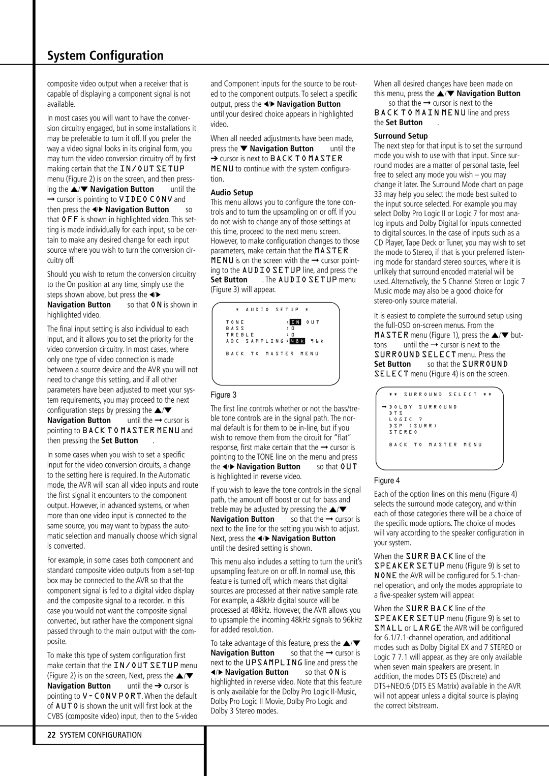
This menu allows you to configure the tone con- trols and to turn the upsampling on or off. If you do not wish to change any of those settings at this time, proceed to the next menu screen. However, to make configuration changes to those parameters, make certain that the MASTER MENU is on the screen with the ➞ cursor point- ing to the AUDIO SETUP line, and press the Set Button F. The AUDIO SETUP menu (Figure 3) will appear.
* | A U D I O S E T U P * |
→ T O N E | | | |
| : | I N | | O U T |
B A S S | | : 0 | | |
T R E B | L E | : 0 | | |
A D C | S A M P L I N G : | 4 8 k | 9 6 k |
B A C K T O M A S T E R M E N U
When all desired changes have been made on this menu, press the ⁄/¤ Navigation Button
Eso that the ➞ cursor is next to the
BACK TO MAIN MENU line and press the Set Button F.
Surround Setup
The next step for that input is to set the surround mode you wish to use with that input. Since sur- round modes are a matter of personal taste, feel free to select any mode you wish – you may change it later. The Surround Mode chart on page 33 may help you select the mode best suited to the input source selected. For example you may select Dolby Pro Logic II or Logic 7 for most ana- log inputs and Dolby Digital for inputs connected to digital sources. In the case of inputs such as a CD Player, Tape Deck or Tuner, you may wish to set the mode to Stereo, if that is your preferred listen- ing mode for standard stereo sources, where it is unlikely that surround encoded material will be used. Alternatively, the 5 Channel Stereo or Logic 7 Music mode may also be a good choice for stereo-only source material.
It is easiest to complete the surround setup using the full-OSDon-screen menus. From the MASTER menu (Figure 1), press the ⁄/¤ but- tons Euntil the ➝ cursor is next to the SURROUND SELECT menu. Press the Set Button Fso that the SURROUND SELECT menu (Figure 4) is on the screen.
tem requirements, you may proceed to the next configuration steps by pressing the ⁄/¤ Navigation Button Euntil the ➞ cursor is pointing to BACK TO MASTER MENU and then pressing the Set Button F.
In some cases when you wish to set a specific input for the video conversion circuits, a change to the setting here is required. In the Automatic mode, the AVR will scan all video inputs and route the first signal it encounters to the component output. However, in advanced systems, or when more than one video input is connected to the same source, you may want to bypass the auto- matic selection and manually choose which signal is converted.
For example, in some cases both component and standard composite video outputs from a set-top box may be connected to the AVR so that the component signal is fed to a digital video display and the composite signal to a recorder. In this case you would not want the composite signal converted, but rather have the component signal passed through to the main output with the com- posite.
To make this type of system configuration first make certain that the IN/OUT SETUP menu (Figure 2) is on the screen, Next, press the ⁄/¤ Navigation Button Euntil the ➔ cursor is pointing to V-CONV PORT. When the default of AUTO is shown the unit will first look at the CVBS (composite video) input, then to the S-video
22SYSTEM CONFIGURATION
Figure 3
The first line controls whether or not the bass/tre- ble tone controls are in the signal path. The nor- mal default is for them to be in-line, but if you wish to remove them from the circuit for “flat” response, first make certain that the ➞ cursor is pointing to the TONE line on the menu and press the ‹/ › Navigation Button Eso that OUT is highlighted in reverse video.
If you wish to leave the tone controls in the signal path, the amount off boost or cut for bass and treble may be adjusted by pressing the ⁄/¤ Navigation Button Eso that the ➞ cursor is next to the line for the setting you wish to adjust. Next, press the ‹/ › Navigation Button E until the desired setting is shown.
This menu also includes a setting to turn the unit’s upsampling feature on or off. In normal use, this feature is turned off, which means that digital sources are processed at their native sample rate. For example, a 48kHz digital source will be processed at 48kHz. However, the AVR allows you to upsample the incoming 48kHz signals to 96kHz for added resolution.
To take advantage of this feature, press the ⁄/¤ Navigation Button Eso that the ➞ cursor is next to the UPSAMPLING line and press the
‹/ › Navigation Button Eso that ON is highlighted in reverse video. Note that this feature is only available for the Dolby Pro Logic II-Music, Dolby Pro Logic II Movie, Dolby Pro Logic and Dolby 3 Stereo modes.
* * S U R R O U N D S E L E C T * *
➞D O L B Y S U R R O U N D D T S
L O G I C | 7 |
D S P ( | S U R R ) |
S T E R E | O |
B A C K T O M A S T E R M E N U
Figure 4
Each of the option lines on this menu (Figure 4) selects the surround mode category, and within each of those categories there will be a choice of the specific mode options. The choice of modes will vary according to the speaker configuration in your system.
When the SURR BACK line of the SPEAKER SETUP menu (Figure 9) is set to NONE the AVR will be configured for 5.1-chan- nel operation, and only the modes appropriate to a five-speaker system will appear.
When the SURR BACK line of the SPEAKER SETUP menu (Figure 9) is set to SMALL or LARGE the AVR will be configured for 6.1/7.1-channel operation, and additional modes such as Dolby Digital EX and 7 STEREO or Logic 7 7.1 will appear, as they are only available when seven main speakers are present. In addition, the modes DTS ES (Discrete) and DTS+NEO:6 (DTS ES Matrix) available in the AVR will not appear unless a digital source is playing the correct bitstream.