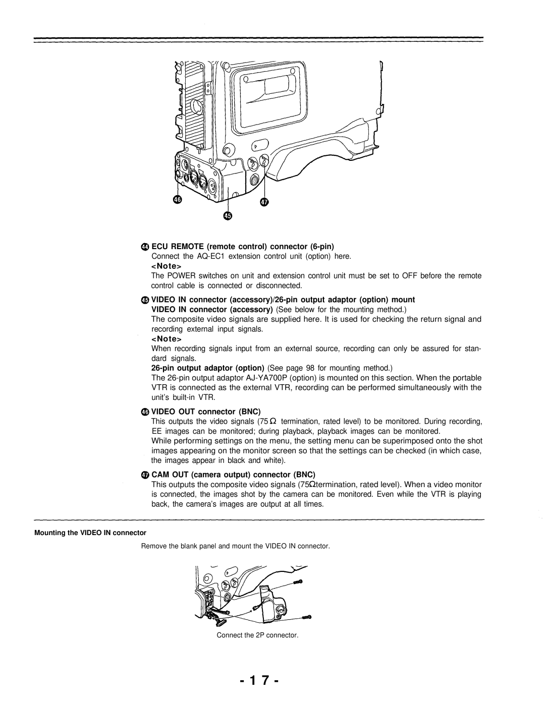
ECU REMOTE (remote control) connector (6-pin)
Connect the
<Note>
The POWER switches on unit and extension control unit must be set to OFF before the remote control cable is connected or disconnected.
VIDEO IN connector
VIDEO IN connector (accessory) (See below for the mounting method.)
The composite video signals are supplied here. It is used for checking the return signal and recording external input signals.
<Note>
When recording signals input from an external source, recording can only be assured for stan- dard signals.
The
VIDEO OUT connector (BNC)
This outputs the video signals (75 ![]() termination, rated level) to be monitored. During recording, EE images can be monitored; during playback, playback images can be monitored.
termination, rated level) to be monitored. During recording, EE images can be monitored; during playback, playback images can be monitored.
While performing settings on the menu, the setting menu can be superimposed onto the shot images appearing on the monitor screen so that the settings can be checked (in which case, the images appear in black and white).
CAM OUT (camera output) connector (BNC)
This outputs the composite video signals (75![]() termination, rated level). When a video monitor is connected, the images shot by the camera can be monitored. Even while the VTR is playing back, the camera’s images are output at all times.
termination, rated level). When a video monitor is connected, the images shot by the camera can be monitored. Even while the VTR is playing back, the camera’s images are output at all times.
Mounting the VIDEO IN connector
Remove the blank panel and mount the VIDEO IN connector.
Connect the 2P connector.
- 1 7 -