Chapter 7 Menu description tables
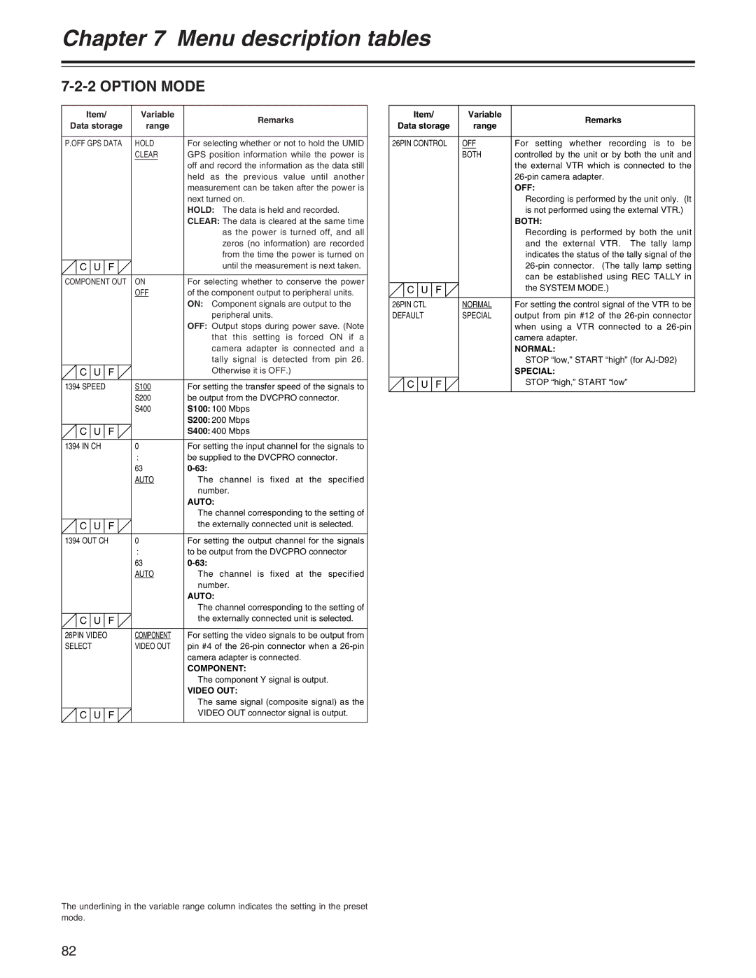
7-2-2 OPTION MODE
Item/ | Variable | Remarks | |
Data storage | range | ||
| |||
|
|
| |
P.OFF GPS DATA | HOLD | For selecting whether or not to hold the UMID | |
| CLEAR | GPS position information while the power is | |
|
| off and record the information as the data still | |
|
| held as the previous value until another | |
|
| measurement can be taken after the power is | |
|
| next turned on. | |
|
| HOLD: The data is held and recorded. | |
|
| CLEAR: The data is cleared at the same time | |
|
| as the power is turned off, and all | |
|
| zeros (no information) are recorded | |
|
| from the time the power is turned on | |
C U F |
| until the measurement is next taken. | |
|
|
| |
COMPONENT OUT | ON | For selecting whether to conserve the power | |
| OFF | of the component output to peripheral units. | |
|
| ON: Component signals are output to the | |
|
| peripheral units. | |
|
| OFF: Output stops during power save. (Note | |
|
| that this setting is forced ON if a | |
|
| camera adapter is connected and a | |
|
| tally signal is detected from pin 26. | |
C U F |
| Otherwise it is OFF.) | |
|
|
| |
1394 SPEED | S100 | For setting the transfer speed of the signals to | |
| S200 | be output from the DVCPRO connector. | |
| S400 | S100: 100 Mbps | |
|
| S200: 200 Mbps | |
C U F |
| S400: 400 Mbps | |
|
|
| |
1394 IN CH | 0 | For setting the input channel for the signals to | |
| : | be supplied to the DVCPRO connector. | |
| 63 | ||
| AUTO | The channel is fixed at the specified | |
|
| number. | |
|
| AUTO: | |
|
| The channel corresponding to the setting of | |
C U F |
| the externally connected unit is selected. | |
|
|
| |
1394 OUT CH | 0 | For setting the output channel for the signals | |
| : | to be output from the DVCPRO connector | |
| 63 | ||
| AUTO | The channel is fixed at the specified | |
|
| number. | |
|
| AUTO: | |
|
| The channel corresponding to the setting of | |
C U F |
| the externally connected unit is selected. | |
|
|
| |
26PIN VIDEO | COMPONENT | For setting the video signals to be output from | |
SELECT | VIDEO OUT | pin #4 of the | |
|
| camera adapter is connected. | |
|
| COMPONENT: | |
|
| The component Y signal is output. | |
|
| VIDEO OUT: | |
|
| The same signal (composite signal) as the | |
C U F |
| VIDEO OUT connector signal is output. | |
|
|
|
Item/ | Variable | Remarks | |
Data storage | range | ||
| |||
|
|
| |
26PIN CONTROL | OFF | For setting whether recording is to be | |
| BOTH | controlled by the unit or by both the unit and | |
|
| the external VTR which is connected to the | |
|
| ||
|
| OFF: | |
|
| Recording is performed by the unit only. (It | |
|
| is not performed using the external VTR.) | |
|
| BOTH: | |
|
| Recording is performed by both the unit | |
|
| and the external VTR. The tally lamp | |
|
| indicates the status of the tally signal of the | |
|
| ||
|
| can be established using REC TALLY in | |
C U F |
| the SYSTEM MODE.) | |
|
|
| |
26PIN CTL | NORMAL | For setting the control signal of the VTR to be | |
DEFAULT | SPECIAL | output from pin #12 of the | |
|
| when using a VTR connected to a | |
|
| camera adapter. | |
|
| NORMAL: | |
|
| STOP “low,” START “high” (for | |
|
| SPECIAL: | |
C U F |
| STOP “high,” START “low” | |
|
|
|
The underlining in the variable range column indicates the setting in the preset mode.
82