Chapter 7 Menu description tables
7-2-4 OUTPUT SEL
Item/ | Variable |
| Remarks |
Data storage | range |
| |
|
| ||
|
|
| |
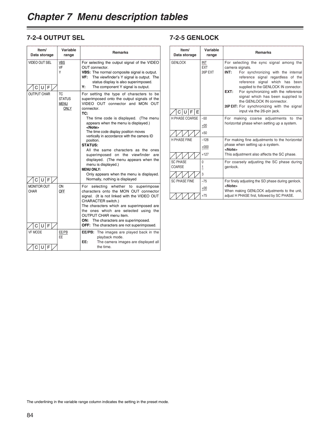
VIDEO OUT SEL | VBS | For selecting the output signal of the VIDEO | |
| VF | OUT connector. | |
| Y | VBS: The normal composite signal is output. | |
|
| VF: The viewfinder’s Y signal is output. The | |
|
|
| status display is also superimposed. |
C U F |
| Y: | The component Y signal is output. |
|
|
| |
OUTPUT CHAR | TC | For setting the type of characters to be | |
| STATUS | superimposed onto the output signals of the | |
| MENU | VIDEO OUT connector and MON OUT | |
| ONLY | connector. | |
|
| TC: |
|
|
| The time code is displayed. (The menu | |
|
| appears when the menu is displayed.) | |
|
| <Note> | |
|
| The time code display position moves | |
|
| vertically in accordance with the camera ID | |
|
| position. | |
|
| STATUS: | |
|
| All the same characters as the ones | |
|
| superimposed on the viewfinder are | |
|
| displayed. (The menu appears when the | |
|
| menu is displayed.) | |
|
| MENU ONLY: | |
|
| Only appears when the menu is displayed. | |
C U F |
| Normally, nothing is displayed | |
|
|
| |
MONITOR OUT | ON | For selecting whether to superimpose | |
CHAR | OFF | characters onto the MON OUT connector | |
|
| signal. (It is not linked with the VIDEO OUT | |
|
| CHARACTER switch.) | |
|
| The characters which are superimposed are | |
|
| the ones which are selected using the | |
|
| OUTPUT CHAR menu item. | |
|
| ON: The characters are superimposed. | |
C U F |
| OFF: The characters are not superimposed. | |
|
|
| |
VF MODE | EE/PB | EE/PB: The images are played back in the | |
| EE |
| playback mode. |
|
| EE: | The camera images are displayed all |
C U F |
|
| the time. |
|
|
|
|
7-2-5 GENLOCK
Item/ | Variable |
|
| Remarks |
|
Data storage | range |
|
|
| |
|
|
|
| ||
|
|
| |||
GENLOCK | INT | For selecting the sync signal among the | |||
| EXT | camera signals. |
| ||
| 26P EXT | INT: | For | synchronizing with the | internal |
|
|
| reference signal regardless of the | ||
|
|
| reference signal which has been | ||
|
|
| supplied to the GENLOCK IN connector. | ||
|
| EXT: For synchronizing with the reference | |||
|
|
| signal which has been supplied to | ||
|
|
| the GENLOCK IN connector. |
| |
|
| 26P EXT: For | synchronizing with the | signal | |
C U F E |
|
| input via the |
| |
|
|
|
|
|
|
H PHASE COARSE | For | making | coarse adjustments | to the | |
| : | horizontal phase when setting up a system. | |||
| +00 | ||||
|
|
|
|
| |
| : |
|
|
|
|
| +50 |
|
|
|
|
|
|
| |||
H PHASE FINE | For making fine adjustments to the horizontal | ||||
| : | phase when setting up a system. |
| ||
| +000 |
| |||
| <Note> |
|
| ||
| : |
|
| ||
| +127 | This adjustment also affects the SC phase. | |||
|
|
| |||
SC PHASE | 0 | For coarsely adjusting the SC phase during | |||
COARSE | 1 | genlock. |
|
| |
| : |
|
|
|
|
| 3 |
|
|
|
|
|
|
| |||
SC PHASE FINE | For finely adjusting the SD phase during genlock. | ||||
| : | <Note> |
|
| |
| +00 |
|
| ||
| When making GENLOCK adjustments to the unit, | ||||
| : | ||||
| +75 | adjust H PHASE first, followed by SC PHASE. | |||
|
|
|
|
|
|
The underlining in the variable range column indicates the setting in the preset mode.
84
